As i was refurbing my heater blower box, i thought i would upgrade the speed fan resistor to a PWM variable controlled one here is how it is done if your interested, not everyone likes this idea and would keep it OEM but my van where necessary i always like to upgrade to modern stuff if required and not that noticeable.
Before starting this upgrade you will need to purchase a PWM Controller this works by a variable controller to allow any motor attached to it to be switched on in a gradual controlled movement instead of a switch that we currently have to control the heater blower in 4 movements.
I purchased a 20amp one as there are various different rated ones on the market, 20amp is enough to not burn out the motor. You can get them with an on/off switch or without i opted for the without, but if you want to kill the power to it completely then get one with a switch. See below pics of each one
so the one on the left is what i purchased, yes its chinese made but isn't most stuff these days, you can buy different models but they all do the same thing, the one on the right has the switch attached to it to isolate the power.
You will also need to buy some wiring, i bought some fresh Brown coloured Earth wire and some crimped connectors. I bought a new blower motor(Brickwerks one), and the heater box refurb kit.
Once you have this stuff you can set about starting, now you will have to remove your dash to do this as you need access to the heater box which has the resistor inside it and the blower motor itself. There are videos online on how to remove your dash if you want to see ahead how its done.
This picture i found on the internet so not mine, but you can see the speed resistor and blower motor in place.
This is a good thing because you can refurb your heater box at the same time and fit a brand new blower motor if required. See below pics.
Heater box taken apart.
Refurb kit for Heater box from Brickwerks
Refurb kit all ready and good to go back together, with blower unit all ready aswell.
So now this has been done you can move onto fitting back in heater box and then removing the speed resistor from the blower motor connections, earth crown and switch, this will not be needed and you should have removed what is in the below picture, i had 2 of these so ignore the one on the right.
As you can see i removed the black/red wire from the switch as this will be used to provide power to the PWM controller, i also used one of the longest yellow wires as my positive wire from the PWM Controller to blower motor, the rest is not needed.
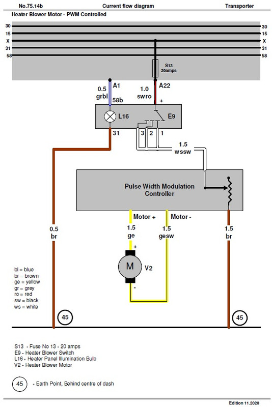
Once you have removed this you can then wire up the PWM controller, here is a wiring diagram of one with a switch but its fairly straight forward to connect if you dont have a switch as there are only 4 wires, Pos/Neg to PWM, then Pos/Neg to motor.
If you look on both Pam the colour coding of the wires and where they go to are shown, the negative from PWM i ran a new earth wire to the earth crowns that sit behind the Fuse Panel. You need to make sure you connect the correct side of the Blower motor aswell or else it will go in reverse. Positive is the top connection on the Blower Motor itself.
Once you have done this and connected the wires up, it would be a good time to test the operation of the blower motor before fitting the top part of the heater box back in, if all good then the heater box can be fitted together completely. The pwm controller i fitted to the left brace bar of the dash and tie wrapped it in place.
The dash panel can go back together now once you have completed this and ready for the next step.
This is where you need to connect the variable switch on the PWM to the heater control panel the one with the sliders on it, a bit of modification is required as the switch is slightly to small to fit through and fix in place with the nut, in order to do this i cut away some of the back of the control panel with a dremmel to allow enough of the thread to sit on the other side so the fixing nut can be tightened on. See Pics
be careful when doing this as cutting away too much might crack the panel its fitted to, this was enough for me on my mod.
as you can see i have cut enough away for me to be able to secure the nut and then i can place this back on the dash carefully, and attach the knob that sits on it.
And that's it job done, i now have a variable controlled heater blower, and i have now dispensed with the switch, and speed resistor that was inside the heater box.
Obviously this is all done at your own risk and if you don't feel upto this sort of task then dont do it. But you will have renewed your blower motor, referred the heater box, and anything else you could do whilst the dash is out. If you got any questions then feel free to ask.
PWM Heater Blower Modification
Moderators: User administrators, Moderators
- steveo9007
- Trader
- Posts: 319
- Joined: 21 May 2019, 17:49
- 80-90 Mem No: 16902
- Location: Cornwall
PWM Heater Blower Modification
1985 RHD Pop Top Autosleeper, 1.7D KY Engine 4 Speed ALD Gearbox (Bertie)
- AngeloEvs
- Registered user
- Posts: 1345
- Joined: 22 Nov 2007, 19:22
- 80-90 Mem No: 4709
- Location: Upwell, Norfolk
Re: PWM Heater Blower Modification
Not sure that you have to remove the dash, I would have though that there is no reason why the PWM feed could not be connected to the cable that is the fastest setting as this goes direct to the Motor. Remove the switch and replace with the potentiometer and Leave the resistors in place as they are not used - unless I have over looked something.
1987 DG Karisma LPG with remodelled interior
- steveo9007
- Trader
- Posts: 319
- Joined: 21 May 2019, 17:49
- 80-90 Mem No: 16902
- Location: Cornwall
Re: PWM Heater Blower Modification
yeah this is true, i refurbed my heater box and was able to totally delete the resistor out of the box. Good shout thoughAngeloEvs wrote: ↑22 Nov 2022, 18:12 Not sure that you have to remove the dash, I would have though that there is no reason why the PWM feed could not be connected to the cable that is the fastest setting as this goes direct to the Motor. Remove the switch and replace with the potentiometer and Leave the resistors in place as they are not used - unless I have over looked something.
1985 RHD Pop Top Autosleeper, 1.7D KY Engine 4 Speed ALD Gearbox (Bertie)
Re: PWM Heater Blower Modification
Fitted one a few years ago but had issues with the potentiometer supplied with Pwm.
Not cheap but replaced with one of these:
https://cpc.farnell.com/vishay/p16-n-1 ... 7-00001003
Not cheap but replaced with one of these:
https://cpc.farnell.com/vishay/p16-n-1 ... 7-00001003
1990 1.9DG 34DAT carb Leisuredrive hightop
- Mocki
- Membership Admin
- Posts: 17027
- Joined: 29 Sep 2005, 09:27
- 80-90 Mem No: 428
- Location: Mansfield Notts
- Contact:
Re: PWM Heater Blower Modification
Ralph , covkid did this years ago, so for further reference viewtopic.php?p=8288545#p8288545
Steve
tel / txt O7947-137911
________________
1989 2.1LpgWBX HiTop Leisuredrive Camper
1988 2.1 Caravelle TS TinTop Camper
tel / txt O7947-137911
________________
1989 2.1LpgWBX HiTop Leisuredrive Camper
1988 2.1 Caravelle TS TinTop Camper
- steveo9007
- Trader
- Posts: 319
- Joined: 21 May 2019, 17:49
- 80-90 Mem No: 16902
- Location: Cornwall
Re: PWM Heater Blower Modification
Guys just asking should I remove this as it’s all ready been covered by Covkid??
1985 RHD Pop Top Autosleeper, 1.7D KY Engine 4 Speed ALD Gearbox (Bertie)
- Aidan
- Trader
- Posts: 6580
- Joined: 11 Oct 2005, 19:21
- 80-90 Mem No: 742
- Location: Llanfyllin, mid Wales : )
- Contact:
Re: PWM Heater Blower Modification
leave it up always good to have fresh content and now this post has the link to Covkids in it is doubly valuable
Re: PWM Heater Blower Modification
That's great. Really well written up
I'll try to get it Archived into Tech or put into the Wiki!
The 80-90 Tech Wikipedia Your 1st port of call
1.9TD Syncro Doka / Syncro Kastenwagen / 16" Kombi Camper
Syncronaut No. 1
1.9TD Syncro Doka / Syncro Kastenwagen / 16" Kombi Camper
Syncronaut No. 1
- Robsey
- Registered user
- Posts: 1203
- Joined: 19 May 2012, 20:45
- 80-90 Mem No: 11137
- Location: East Manchester
Re: PWM Heater Blower Modification
I have done this too, but with a higher rated PWM unit.
The PWM is more likely to burn out than the motor.
( Setting aside "Chinese Quality" )
The motor will only take the current it needs.
If you retain the original / old motor, then brush wear, dirty commutator, and dry or worn bearings would cause the motor to pull more current.
In your case, a new, decent quality fan-motor will be a lot more efficient and run at a lower current.
I think the whole fan-motor and resistor circuit is fused at 20 amps, so selecting a 20 amp PWM unit means that it is running at, or close to it's limit when you have the potentiometer ( 'pot' ) cranked up.
Correction - the current will be more continuous rather than in shorter pulses.
I fitted a unit rated at more than double that, so the PWM unit is never going to break into a sweat.
Even at the point of most effort - the initial cranking-up of the fan-motor from dead-stop.
Lastly - to save hacking the heater panel switch, I used it as an on/off switch, and put the "pot" in the back of my glove box. I rarely need to change the speed setting.
Here is the wiring diagram for mine...
1983 Tin Top with a poorly DF and 4 speed DT box.
1987 Electrics and a DJ engine.
Maybe one day I might get it finished
1987 Electrics and a DJ engine.
Maybe one day I might get it finished