That's more like the Maplins one I remember, thanks for posting.bigbadbob76 wrote:Ok. Here's a quick fag packet drawing. This should work.
.
Fuel Gauge/Sender Variants
Moderators: User administrators, Moderators
-
bigherb

- Registered user
- Posts: 2579
- Joined: 27 Mar 2008, 13:50
- 80-90 Mem No: 5789
- Location: West Kent
Re: Fuel Gauge/Sender Variants

1982 Camper 1970 1500 Beetle Various Skoda's, Ariel Arrow
-
bigbadbob76

- Registered user
- Posts: 1733
- Joined: 07 Nov 2016, 14:41
- 80-90 Mem No: 15707
- Location: Isle of Skye
Re: Fuel Gauge/Sender Variants
bigherb wrote: thanks for posting.
No problem, glad to help.
That's just an off the top of the head design so don't set too much store by it until we iron out any issues.
We might find we need different values of Zd1 for different early/late senders or might not need it at all.
Time and experimentation will tell.
'86 1.9 DG, 4 spd, tintop, camper conversion.
Split case club member.
Split case club member.

Re: Fuel Gauge/Sender Variants
CJH wrote:bigbadbob76 wrote:The gauge draws quite a bit of current (350mA when full) so don't use a weedy little vr or it will smoke. Haha.
Thanks for the tip - I don't think any of the ones I have on order will be up to the job. I'll get a general purpose potentiometer from RS in that case.
Second thoughts - 10V and 350mA makes for too much power for a cheap general purpose potentiometer. Even if I stick to the higher end of the sender resistance range, the power is still 0.5 to 1W, which would make the potentiometer quite expensive. So I'll do the test with a variety of combinations of fixed resistors. I have some 2W 120 Ohm resistors, so in various combinations I can make 40, 60, 120, 140, 144, 150, 160, 180, 240 - that should give me enough sample points I think.
"I'm a man of means, by no means....King of the Road!"
1983 Viking Xplorer, 2.1DJ
1983 Viking Xplorer, 2.1DJ
-
bigbadbob76
- Registered user
- Posts: 1733
- Joined: 07 Nov 2016, 14:41
- 80-90 Mem No: 15707
- Location: Isle of Skye
Re: Fuel Gauge/Sender Variants
Good plan. 
350mA is a ballpark figure but you need to be able to cope with that if your sensor pot was turned all the way to "full".
At the lower end of the gauge range you'll have less current.
I assume you're using a 10v regulator to supply the gauge on the bench.
Ignoring the gauge resistance and rounding up the wattage for safety's sake,
10v/40 ohm = 250mA @ 2.5W total or 1.25w per resistor.
10v/60 ohm = 166mA @ 2W or 1w per resistor
10v/120ohm = 83mA @ 1W total and it gets better as you go higher in resistance.
All ballpark figures, we'll get the true ones we need when you do the tests.
'86 1.9 DG, 4 spd, tintop, camper conversion.
Split case club member.
Split case club member.
Re: Fuel Gauge/Sender Variants
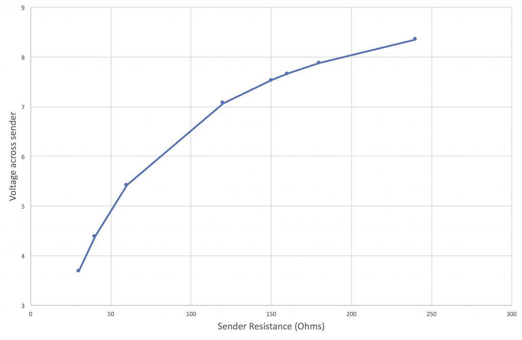
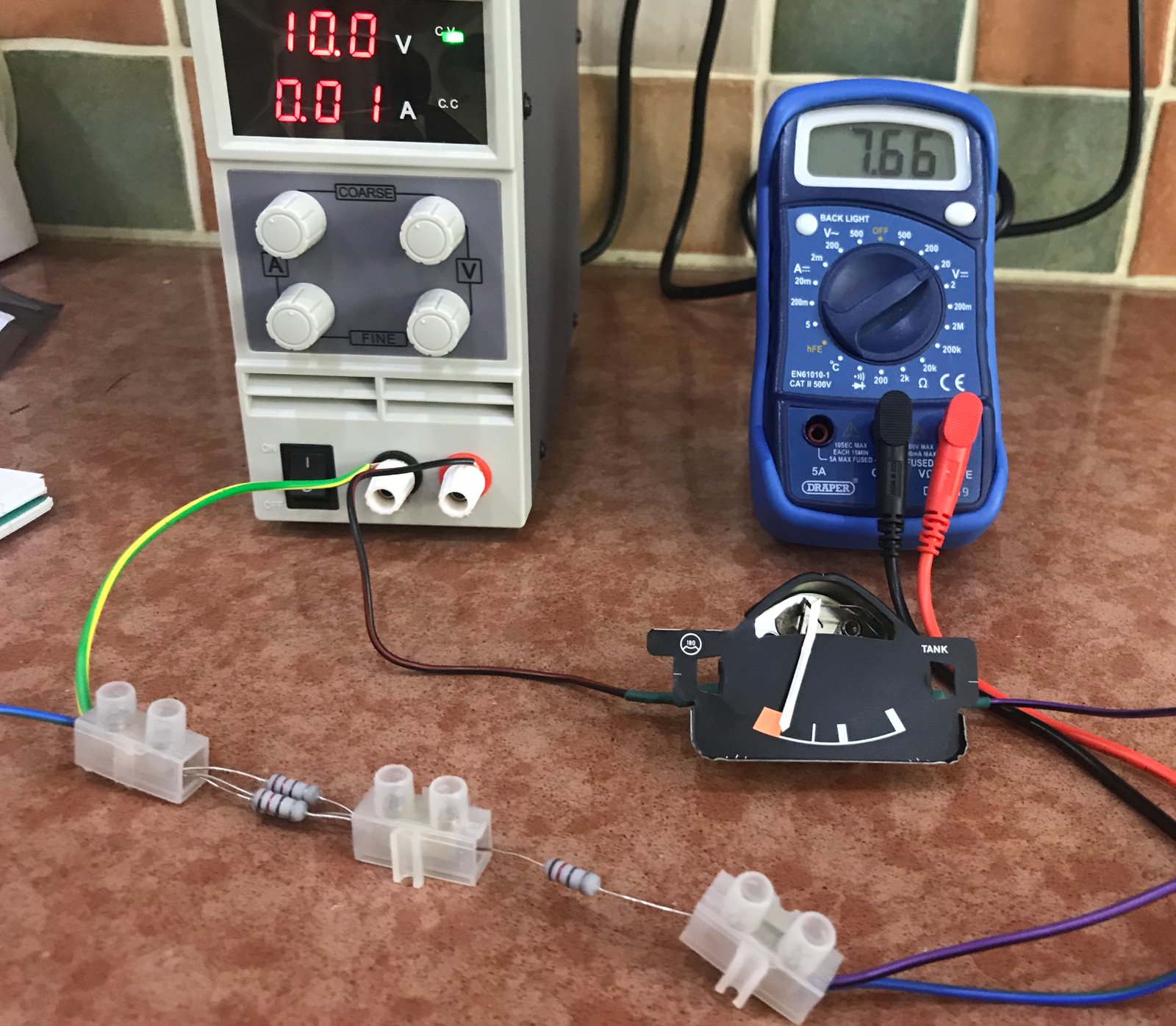
I made some measurements. I used a bench power supply set to 10V. Here's my test setup:

The voltmeter is connected to the blue wires exiting the first and last chocolate blocks. I used various combinations of 120 ohm resistors to get measurements at 30, 40, 60, 120, 150, 160, 180 and 240 ohms. The results are as follows:
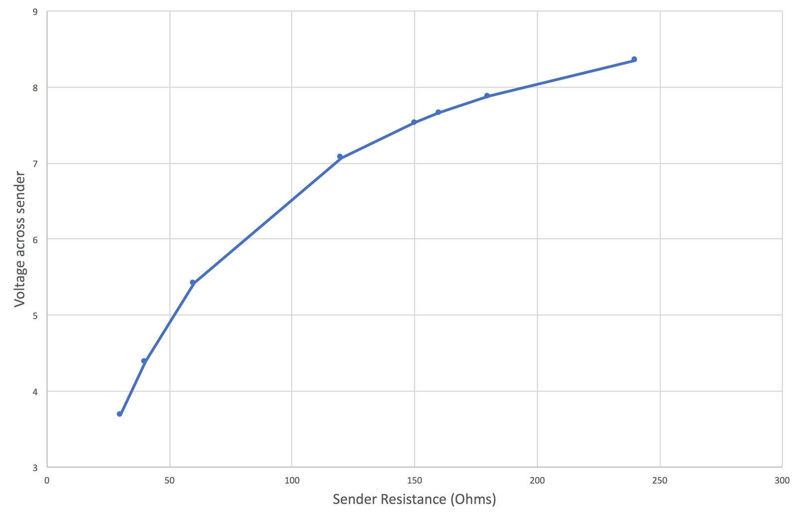
30 ohms: 3.69V
40 ohms: 4.39V
60 ohms: 5.42V
120 ohms: 7.07V
150 ohms: 7.53V
160 ohms: 7.66V
180 ohms: 7.88V
240 ohms: 8.35V
Plotted as a chart they look like this:
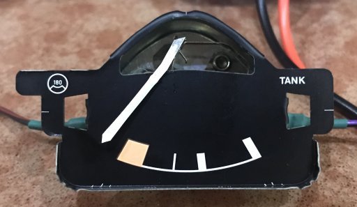
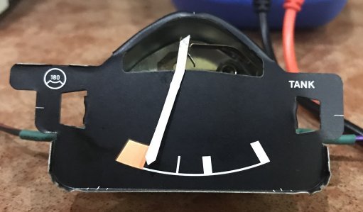
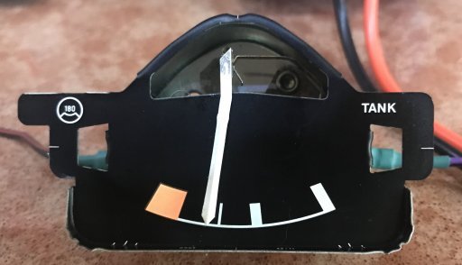
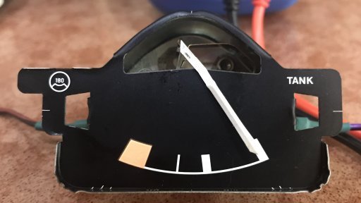
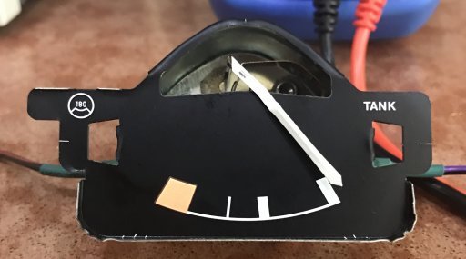
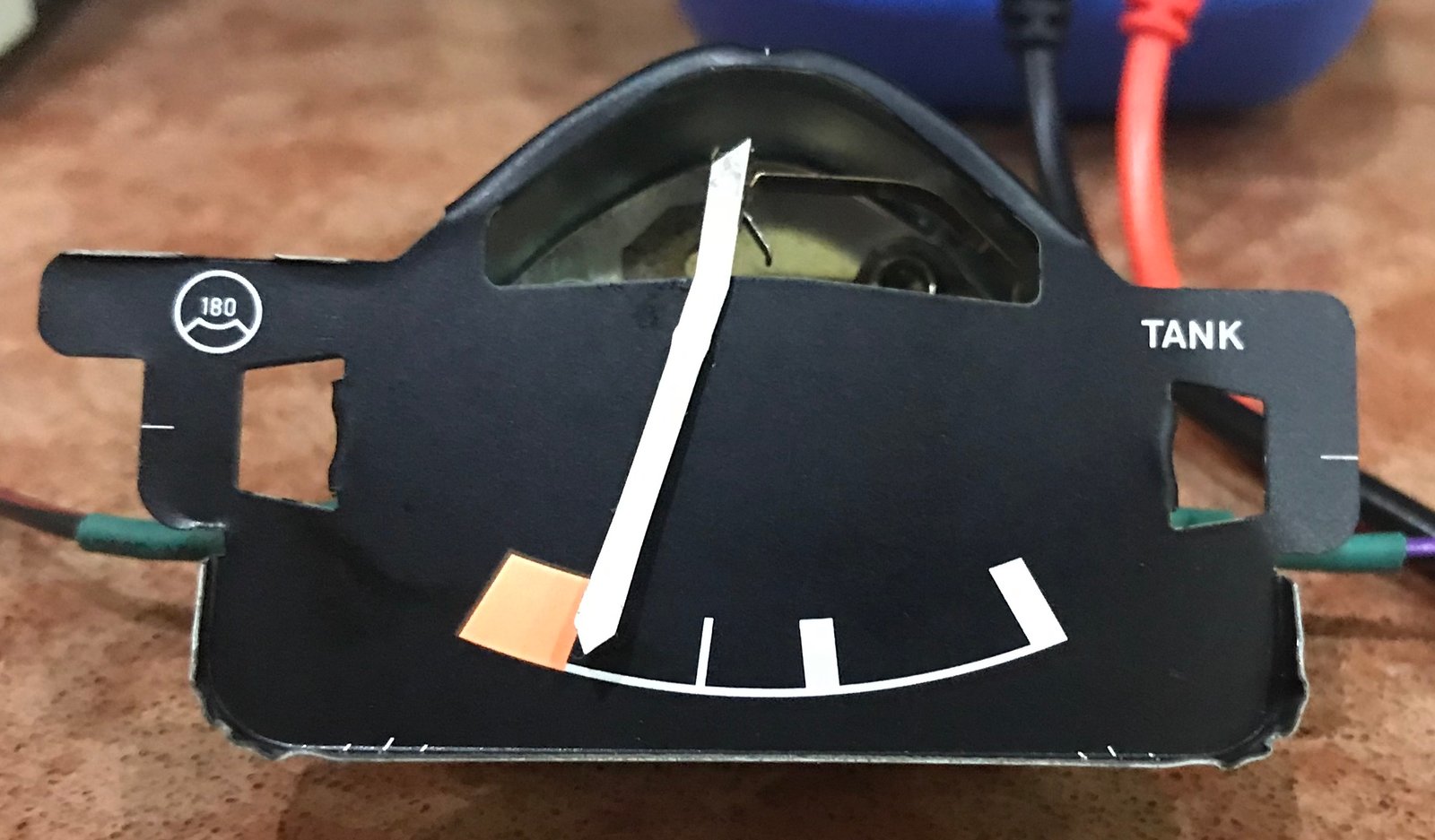
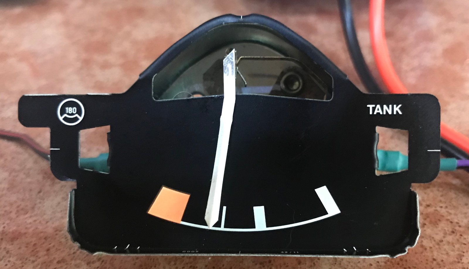
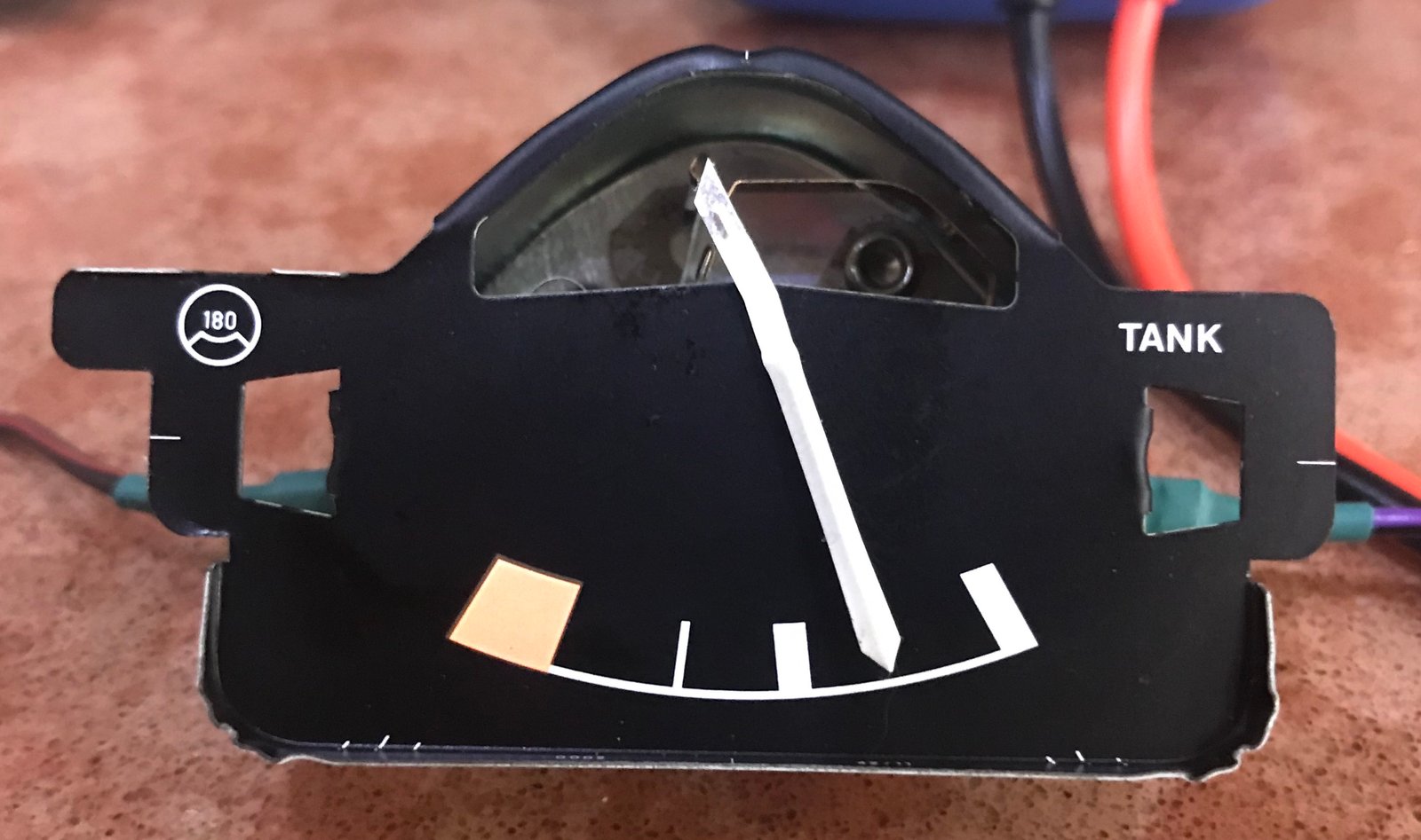
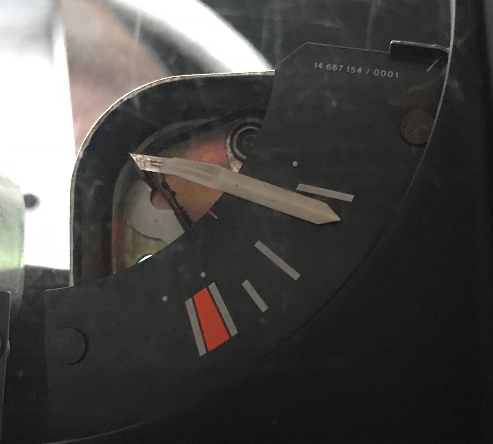
And here's what the gauge looked like at each step:
At rest (unpowered):
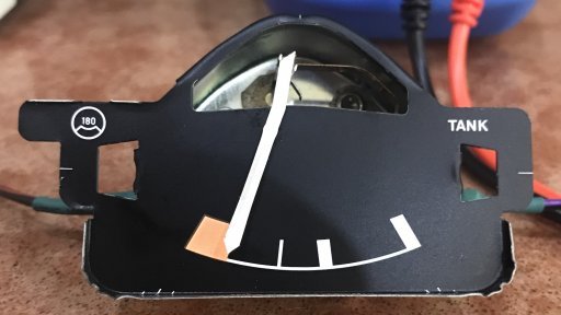
240 ohms:
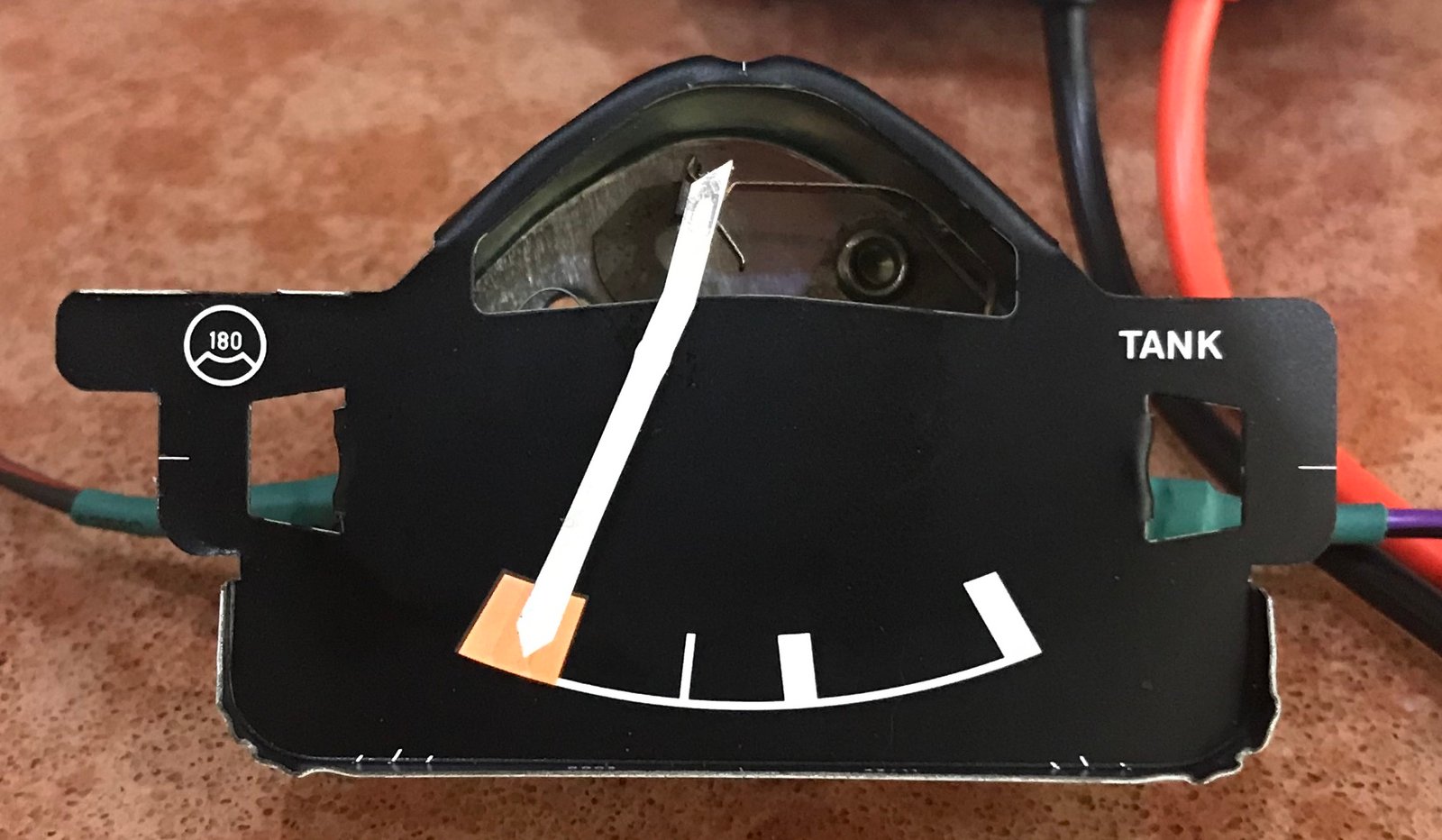
180 ohms:

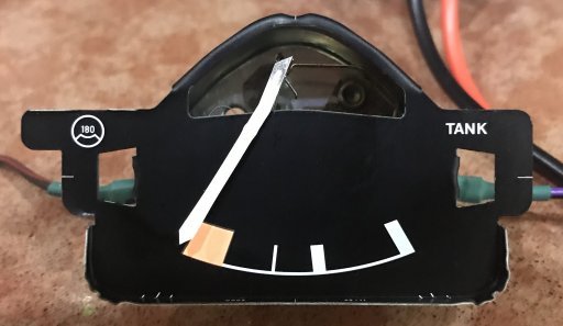
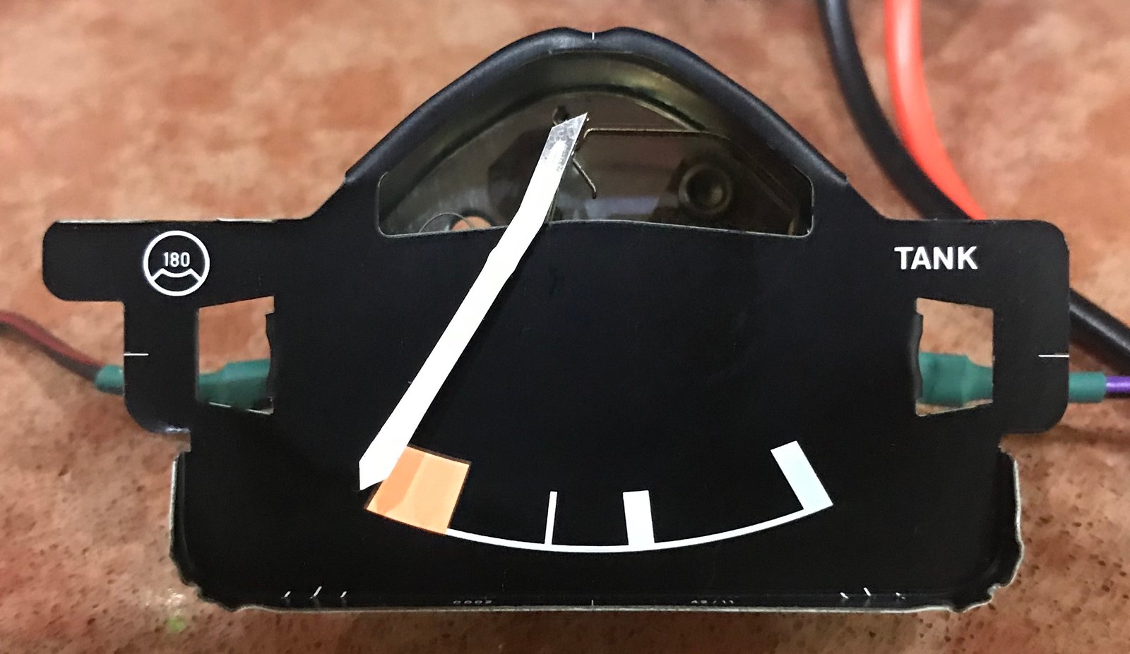
160 ohms:
150 ohms:
120 ohms:
60 ohms:

40 ohms:
30 ohms:
I'd say 160 ohms looks like the right place to trigger the warning LED (so 7.66V), since the needle is just entering the red part of the gauge. That seems to correspond to Bigherb's photo for 10 litres in the tank. But for the later sender, that's only 8 ohms away from totally empty, so may not provide enough of a warning to be useful. Evidently it's going to be useful to be able to tune the switching point - is that what VR1 will allow?
The voltmeter is connected to the blue wires exiting the first and last chocolate blocks. I used various combinations of 120 ohm resistors to get measurements at 30, 40, 60, 120, 150, 160, 180 and 240 ohms. The results are as follows:
30 ohms: 3.69V
40 ohms: 4.39V
60 ohms: 5.42V
120 ohms: 7.07V
150 ohms: 7.53V
160 ohms: 7.66V
180 ohms: 7.88V
240 ohms: 8.35V
Plotted as a chart they look like this:
And here's what the gauge looked like at each step:
At rest (unpowered):

240 ohms:
180 ohms:
160 ohms:

150 ohms:
120 ohms:
60 ohms:
40 ohms:
30 ohms:

I'd say 160 ohms looks like the right place to trigger the warning LED (so 7.66V), since the needle is just entering the red part of the gauge. That seems to correspond to Bigherb's photo for 10 litres in the tank. But for the later sender, that's only 8 ohms away from totally empty, so may not provide enough of a warning to be useful. Evidently it's going to be useful to be able to tune the switching point - is that what VR1 will allow?
"I'm a man of means, by no means....King of the Road!"
1983 Viking Xplorer, 2.1DJ
1983 Viking Xplorer, 2.1DJ
Re: Fuel Gauge/Sender Variants
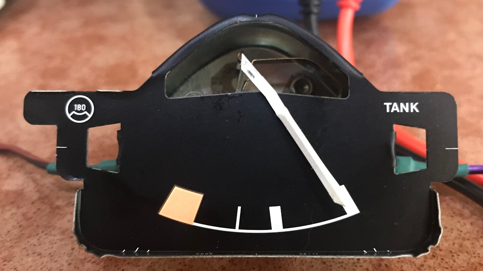
CJH wrote: 180 ohms:
Given that the part number for the gauges didn't change when the senders changed, one thing that seems odd about these results is that the newer sender will never generate a resistance high enough to put the needle this far into the red - it only goes up to 168 ohms apparently. That doesn't seem right. I'll bet people with late vans have seen their needles further into the red than this.
"I'm a man of means, by no means....King of the Road!"
1983 Viking Xplorer, 2.1DJ
1983 Viking Xplorer, 2.1DJ
-
937carrera

- Registered user
- Posts: 3599
- Joined: 05 Apr 2015, 19:29
- 80-90 Mem No: 16333
- Location: N Yorks.
Re: Fuel Gauge/Sender Variants
I have a late van - definitely goes further to the left without running out of fuel. (all the way to the edge of the red)
1981 RHD 2.0 Aircooled Leisuredrive project, CU engine
1990 RHD 1.9 Auto Sleeper with DF/DG engine
1990 RHD 1.9 Auto Sleeper with DF/DG engine
-
bigbadbob76
- Registered user
- Posts: 1733
- Joined: 07 Nov 2016, 14:41
- 80-90 Mem No: 15707
- Location: Isle of Skye
Re: Fuel Gauge/Sender Variants
Great stuff Chris.
Loads of good data there.
I'll do some sums and suggest some component values for a try.
I'm pretty sure I've been further than that in the red right enough, as Carrera says.
I usually fill up around 300 miles because I don't trust the gauge.
Maybe the float arm on the early senders doesn't let the resistance sweep over the full arc so it never gets the resistance to it's full maximum.
If I had a warning light that I'd calibrated myself I might trust it more.
I assume you waited for a while for the gauge needle to settle, the hot wire meters take a while to move so they damp the readings and don't jump around.
'86 1.9 DG, 4 spd, tintop, camper conversion.
Split case club member.
Split case club member.
Re: Fuel Gauge/Sender Variants
937carrera wrote:I have a late van - definitely goes further to the left without running out of fuel. (all the way to the edge of the red)
I'd better check the sender values again in that case - I may have made a slip in converting the VW1301 'resistance units' to Ohms.
"I'm a man of means, by no means....King of the Road!"
1983 Viking Xplorer, 2.1DJ
1983 Viking Xplorer, 2.1DJ
Re: Fuel Gauge/Sender Variants
bigbadbob76 wrote: I assume you waited for a while for the gauge needle to settle, the hot wire meters take a while to move so they damp the readings and don't jump around.
Yes, I did - made sure it had stopped moving before I took the photo. The voltage settled almost instantly.
"I'm a man of means, by no means....King of the Road!"
1983 Viking Xplorer, 2.1DJ
1983 Viking Xplorer, 2.1DJ
-
937carrera
- Registered user
- Posts: 3599
- Joined: 05 Apr 2015, 19:29
- 80-90 Mem No: 16333
- Location: N Yorks.
Re: Fuel Gauge/Sender Variants
You probably know this already, but as I just looked this up trying to find some specified values, the change of sender unit happened in 1987 model year when the suffix went from E to K. The gauge was the same part 81 to 90.
Found this on an old bulletin board posting
http://gerry.vanagon.com/cgi-bin/wa.exe ... P=2413&F=P
Found this on an old bulletin board posting
http://gerry.vanagon.com/cgi-bin/wa.exe ... P=2413&F=P
1981 RHD 2.0 Aircooled Leisuredrive project, CU engine
1990 RHD 1.9 Auto Sleeper with DF/DG engine
1990 RHD 1.9 Auto Sleeper with DF/DG engine
-
bigbadbob76
- Registered user
- Posts: 1733
- Joined: 07 Nov 2016, 14:41
- 80-90 Mem No: 15707
- Location: Isle of Skye
Fuel Gauge/Sender Variants
Ok. Try this.

R1 limits the zener and base-emitter current in case of the sender going open circuit.
Rv should give a bit of adjustment, you want it as high as possible while still providing enough current to turn on the transistor.
When the led is on, ZD1 is conducting and the combined resistance of zd1, R1, RV1 and the transistor will be in parallel with the sender and will lower it's efective resistance and the gauge might rise slightly but once you're in the red, you're in the red. the gauge aint that accurate.
Only testing will beat the theory now.
The transistor can be any NPN small signal/general purpose one.
I just checked mine.
6.22v at half full.

'86 1.9 DG, 4 spd, tintop, camper conversion.
Split case club member.
Split case club member.
Re: Fuel Gauge/Sender Variants
937carrera wrote:You probably know this already, but as I just looked this up trying to find some specified values, the change of sender unit happened in 1987 model year when the suffix went from E to K. The gauge was the same part 81 to 90.
Found this on an old bulletin board posting
http://gerry.vanagon.com/cgi-bin/wa.exe ... P=2413&F=P
That's an interesting find. As it says, Bentley shows that change to the resistance ranges happened between 1984 and 1985. The conversion from VW1301 'resistance units' to ohms is different in that thread to what I found though.
So Bentley says that the 1980-1984 sender will range from 55 resistance units to 560. This link to Bentley's web page says that 55 is equivalent to 37 Ohms and 560 is equivalent to 288 Ohms
Bentley then says that the 1985- sender ranges from 50 to 320 units, corresponding to 34 to 168 Ohms.
I wonder if the values in the link you found will make more sense of my measurements and needle positions - I'll take a look.
"I'm a man of means, by no means....King of the Road!"
1983 Viking Xplorer, 2.1DJ
1983 Viking Xplorer, 2.1DJ
Re: Fuel Gauge/Sender Variants
bigbadbob76 wrote:Ok. Try this.
Thank you - I'll give that a try. Can I change any of those component values without affecting the circuit? For R1 I have a ready supply of 120 ohm resistors, and for RV1 I have some 500 Ohms versions arriving soon - I assume that combination should work?
I assume the zener value of 6.8V is chosen because we're aiming to be above about 7.5V when the LED lights up, so the zener keeps the transistor out of the circuit for most of the time. I have some 5.6V zeners to hand - if I was to use one of those, presumably the circuit would function the same except the transistor would be in the circuit from 5.6V upwards.
Did you remove the damping circuit deliberately?
bigbadbob76 wrote:I just checked mine.
6.22v at half full.
That seems consistent. I checked mine too: 66.7 Ohms, 5.63V (which seem consistent with earlier measurements) but the needle seems to sit higher than expected for those values.
"I'm a man of means, by no means....King of the Road!"
1983 Viking Xplorer, 2.1DJ
1983 Viking Xplorer, 2.1DJ
-
bigbadbob76
- Registered user
- Posts: 1733
- Joined: 07 Nov 2016, 14:41
- 80-90 Mem No: 15707
- Location: Isle of Skye
Re: Fuel Gauge/Sender Variants
one answer to the two different senders for the same gauge is if there was an extra resistor on the early PCB in parallel with the sender.
Anyone found one?
Hang on, I'll do the maths for 5.6v/120 ohm and 500 ohm......
Anyone found one?
Hang on, I'll do the maths for 5.6v/120 ohm and 500 ohm......
'86 1.9 DG, 4 spd, tintop, camper conversion.
Split case club member.
Split case club member.