Page 1 of 11
Fuel Gauge/Sender Variants
Posted: 23 Jul 2018, 15:25
by CJH
I was doing some sums to figure out what resistor values to use to make a 'low fuel' warning lamp circuit (see
this thread). I checked Bentley for the resistance specs for the fuel sender, and it seems there are two different versions:
1980-1984: Full=37 Ohms, Empty=288 Ohms
From 1985: Full=34 Ohms, Empty=168 Ohms
So it made me wonder what will happen when a new fuel gauge is used with an old sender, or vice versa. Are the senders fairly linear? When a post-85 sender registers empty at 168 Ohms, that's roughly half the way down the range of an earlier sender, so would an earlier gauge still register half full? And would a later gauge show as empty if used with an early sender that's still got half a tank left?
I've got a 1983 van, so I can only assume that it's still got an early sender in the tank. But I've recently fitted a fuel gauge from a tacho dash, and I don't know what year van it came from. Thankfully, if there's a mismatch, it's likely to mean that the gauge will show empty sooner than it should - probably the safer type of mismatch.
Is this a known problem? Are the senders and gauges sufficiently linear that the problem will be around the half-way point, or are they non-linear such that 168 Ohms is nearly empty even in the earlier sender?
Re: Fuel Gauge/Sender Variants
Posted: 23 Jul 2018, 15:49
by CJH
Hmm - that's odd. 7zap shows the same fuel gauge for tacho variants for both a 1983 and a 1987 model: 255919031
So somehow the same gauge works with both types of sender: 251919051E for early and 251919051K for late. So I guess it can't be a linear sender in that case. Maybe 168 Ohms is going to show empty on both gauges, but 288 Ohms is going to show *really* empty.
Choosing the resistor values for my low fuel LED means picking a sender resistance at which the LED should come on. 130ish Ohms might be about right for a sender that goes from 34 to 168 Ohms, but intuitively it seems to be far too low a value for a sender that goes from 37 to 288 Ohms.
Re: Fuel Gauge/Sender Variants
Posted: 24 Jul 2018, 07:09
by bigherb
CJH wrote:
1980-1984: Full=37 Ohms, Empty=288 Ohms
From 1985: Full=34 Ohms, Empty=168 Ohms
So it made me wonder what will happen when a new fuel gauge is used with an old sender, or vice versa. Are the senders fairly linear? When a post-85 sender registers empty at 168 Ohms, that's roughly half the way down the range of an earlier sender, so would an earlier gauge still register half full? And would a later gauge show as empty if used with an early sender that's still got half a tank left?
Actually, it runs out of fuel when you are just in the reserve.
And no fuel gauges aren't normally linear (modern vehicles with electronic dashes usually are). gauges are less accurate nearer full, that's why they drop quicker to near half a tank and the shape of the fuel tank makes them even less linear on T25's. Temperature gauges work the same as well.
Re: Fuel Gauge/Sender Variants
Posted: 24 Jul 2018, 07:24
by CJH
Thanks. I think I'll take some resistance measurements as I use up the current tank, with a view to deciding on a point at which the warning light ought to come on. The trim pot in that circuit allows for some adjustment, but if I was looking for, say, 75% of the distance between the lowest and highest resistance for the two types of sender, then it turns out that both the fixed resistor and the range of the variable resistor would have to be quite different. If there was a common resistance value for both senders that would indicate 'nearly empty', that would make life easier. Is that likely do you think?
Re: Fuel Gauge/Sender Variants
Posted: 24 Jul 2018, 08:39
by bigherb
CJH wrote: If there was a common resistance value for both senders that would indicate 'nearly empty', that would make life easier. Is that likely do you think?
Probably not.
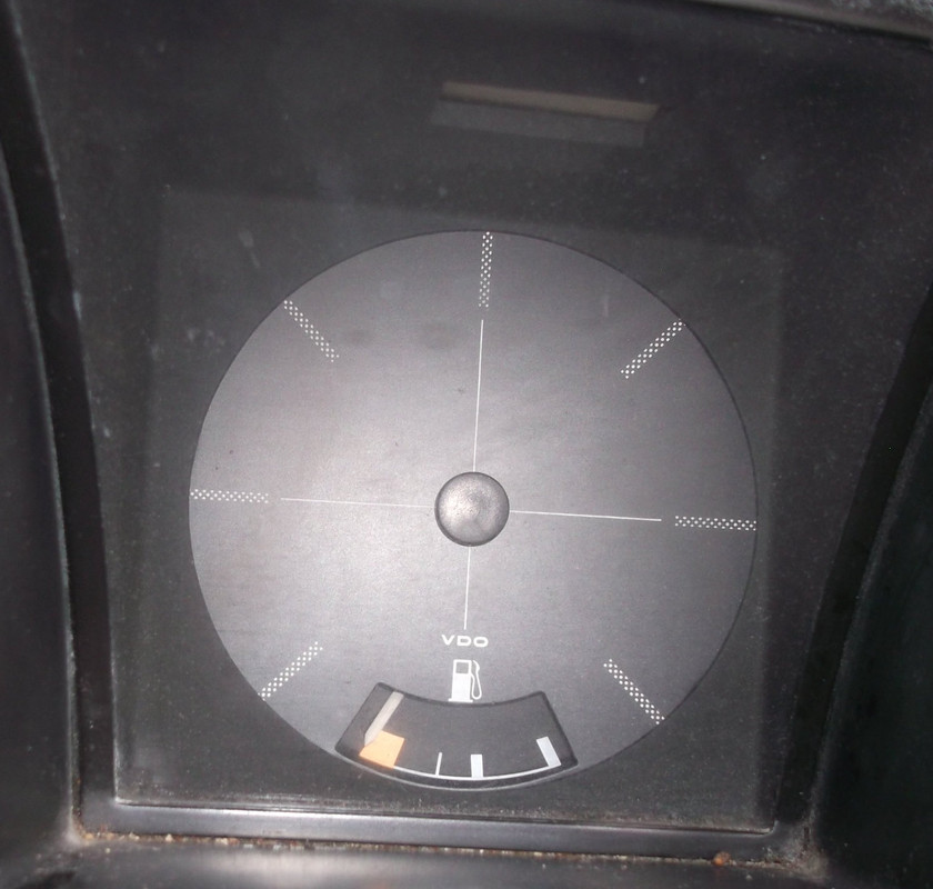
I did this in another thread
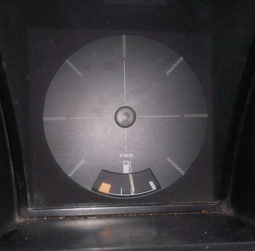
But you can see the angle of deflection of the needle decreases the higher the gauge reading.
5l
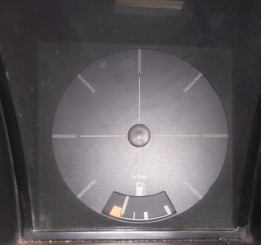
10l
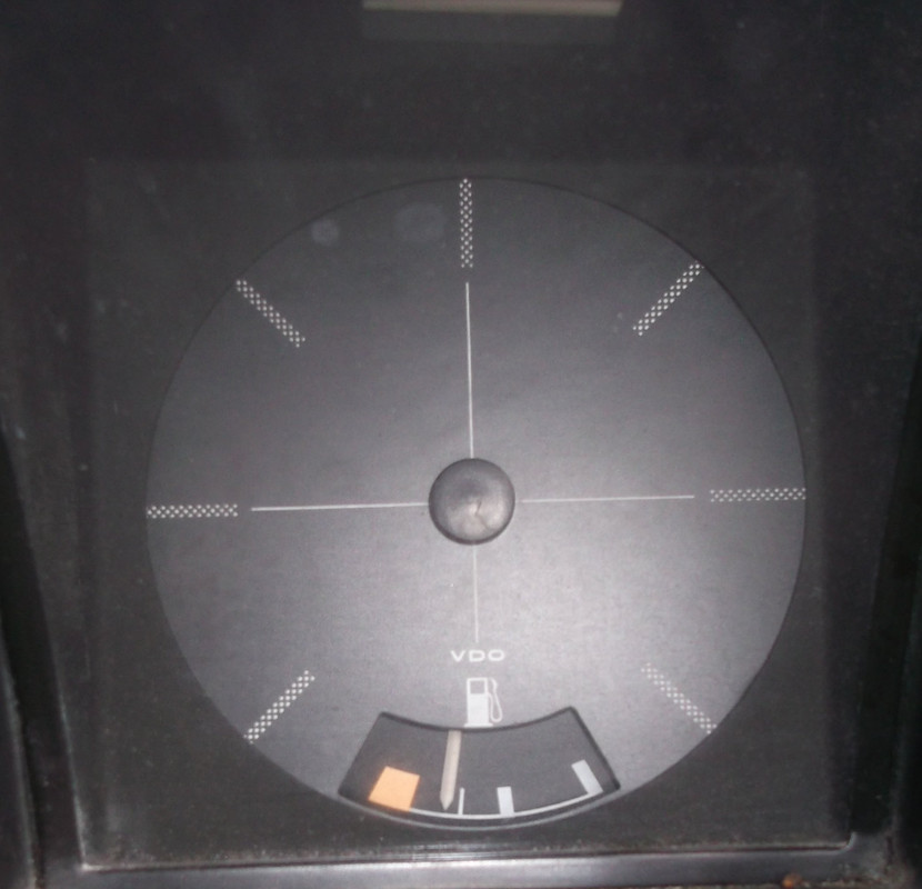
15l
20l
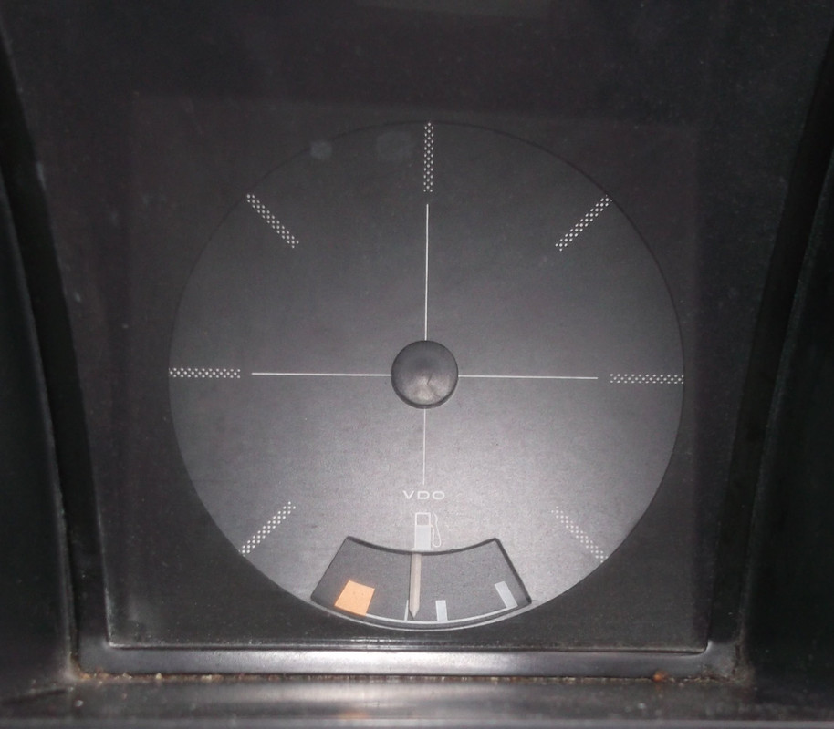
25l
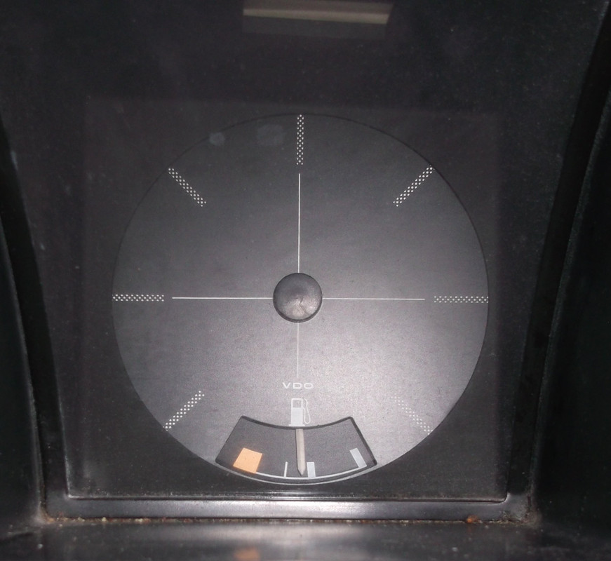
Then to 35l
Re: Fuel Gauge/Sender Variants
Posted: 24 Jul 2018, 09:33
by CovKid
No only is it not linear, its useless when parked and wildly inaccurate as you drive around bends. The only two reference points I've ever found to be near correct are full or empty,

I looked at this a while back and concluded I'd need to at least figure out at what point it conks out and fit an adjustable pot so I could configure the trigger point myself.
Re: Fuel Gauge/Sender Variants
Posted: 24 Jul 2018, 10:57
by 937carrera
Not only left / right, up and down hills too. I've come to the conclusion that the only time the fuel gauge is anywhere near accurate is when you are parked on level ground.
Is there a bit of circuitry that could be added to dampen these oscillations - say average the reading over 5 minutes, other cars don't have this problem
Re: Fuel Gauge/Sender Variants
Posted: 24 Jul 2018, 11:30
by CJH
bigherb wrote:
I did this in another thread
But you can see the angle off deflection off the needle decreases the higher the gauge reading.
5l
Thank you - that's interesting. I was planning to take resistance measurements as my tank gradually empties, but since I won't actually know how much fuel is in the tank, all that will tell me is where the needle sits for a given resistance, and I could just as easily do that by connecting the gauge up to an external variable resistor - I have some on order to try out in my warning lamp board.
Judging by how incredibly lonely your fuel gauge looks I'm assuming that's an Aircooled dash, so you presumably have the 1980-84 sender in your tank, as I do. So in fact I can adjust my variable resistor to make the needle sit in the same place as your 5l, 10l, 15l etc steps and then I'll be able to make the link.
I do have some variable resistors on order that have a very large range, and they would potentially allow the point when the LED is triggered to be adjusted for either sender - the downside of the large range will be that they might be more difficult to fine tune because one turn of the adjuster has a bigger effect on the resistance.
I do realise that the LED won't be as stable and reliable as a modern dash, but anything that reminds me to look at the fuel gauge will be a benefit I think.
Re: Fuel Gauge/Sender Variants
Posted: 24 Jul 2018, 12:04
by itchyfeet
bear in mind this could add a significant resistance, it's the sender earth connetion to the body where you can't get to it and almost certainly very rusty

Re: Fuel Gauge/Sender Variants
Posted: 24 Jul 2018, 12:09
by CJH
Yeah, it's wonder these gauges work at all.
Re: Fuel Gauge/Sender Variants
Posted: 24 Jul 2018, 13:12
by bigherb
CJH wrote:
Judging by how incredibly lonely your fuel gauge looks I'm assuming that's an Aircooled dash, so you presumably have the 1980-84 sender in your tank,
Yes it was.
CJH wrote:
I do realise that the LED won't be as stable and reliable as a modern dash, but anything that reminds me to look at the fuel gauge will be a benefit I think.
I would put a small capacitor across the circuit to stabilise the light from rapidly flashing on and off when around the trigger point from the fuel slopping about.
Re: Fuel Gauge/Sender Variants
Posted: 24 Jul 2018, 13:26
by CJH
That seems like a sensible suggestion, but do you have any idea where in the circuit, or what value?
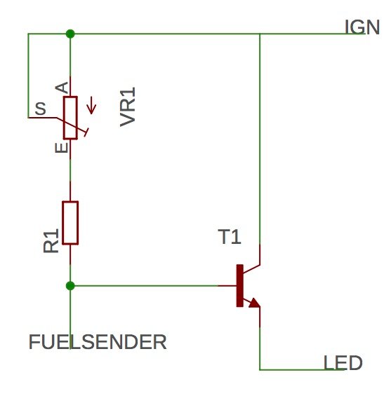
I think there are two possible places it could go:
1) Between the transistor and R1, to smooth the feed to the transistor base.
2) On the fuel sender input, to smooth the sender signal.
My little test board doesn't have a space for such a capacitor, but I can bodge one into the circuit fairly easily I think, in order to test different values. But some idea what sort of value to start with would be useful.
Re: Fuel Gauge/Sender Variants
Posted: 24 Jul 2018, 14:47
by bigherb
CJH wrote:
I think there are two possible places it could go:
1) Between the transistor and R1, to smooth the feed to the transistor base.
2) On the fuel sender input, to smooth the sender signal.
Probably not without extra circuitry. Easiest would be to the LED and it would just dim out as the capacitor discharges might need a blocking diode between the capacitor/LED and T1 as well. Capacitor size depends on how long you want the LED to stay on and the power consumption of the LED
Re: Fuel Gauge/Sender Variants
Posted: 24 Jul 2018, 15:24
by AngeloEvs
Different senders - possible differences in fuel tanks, profile, etc? Pretty sure I have seen fuel tanks listed for pre 85 vans and they do look different. Tested quite a few early and late dash pods and, at 100 ohms, the needle sat more or less just under half full.
Re: Fuel Gauge/Sender Variants
Posted: 24 Jul 2018, 18:01
by bigbadbob76
Interesting study by yourself again Chris, and thanks for the info BigHerb and Angelo.

Would a 10 turn trim pot help you Chris?
I think you might want to feed the circuit from the 10V regulator too.

How is the circuit going to effect your gauge reading too? it'll be adding resistance in parallel with the sender.
I'm not dissing your idea, just throwing a few things in the pot.
