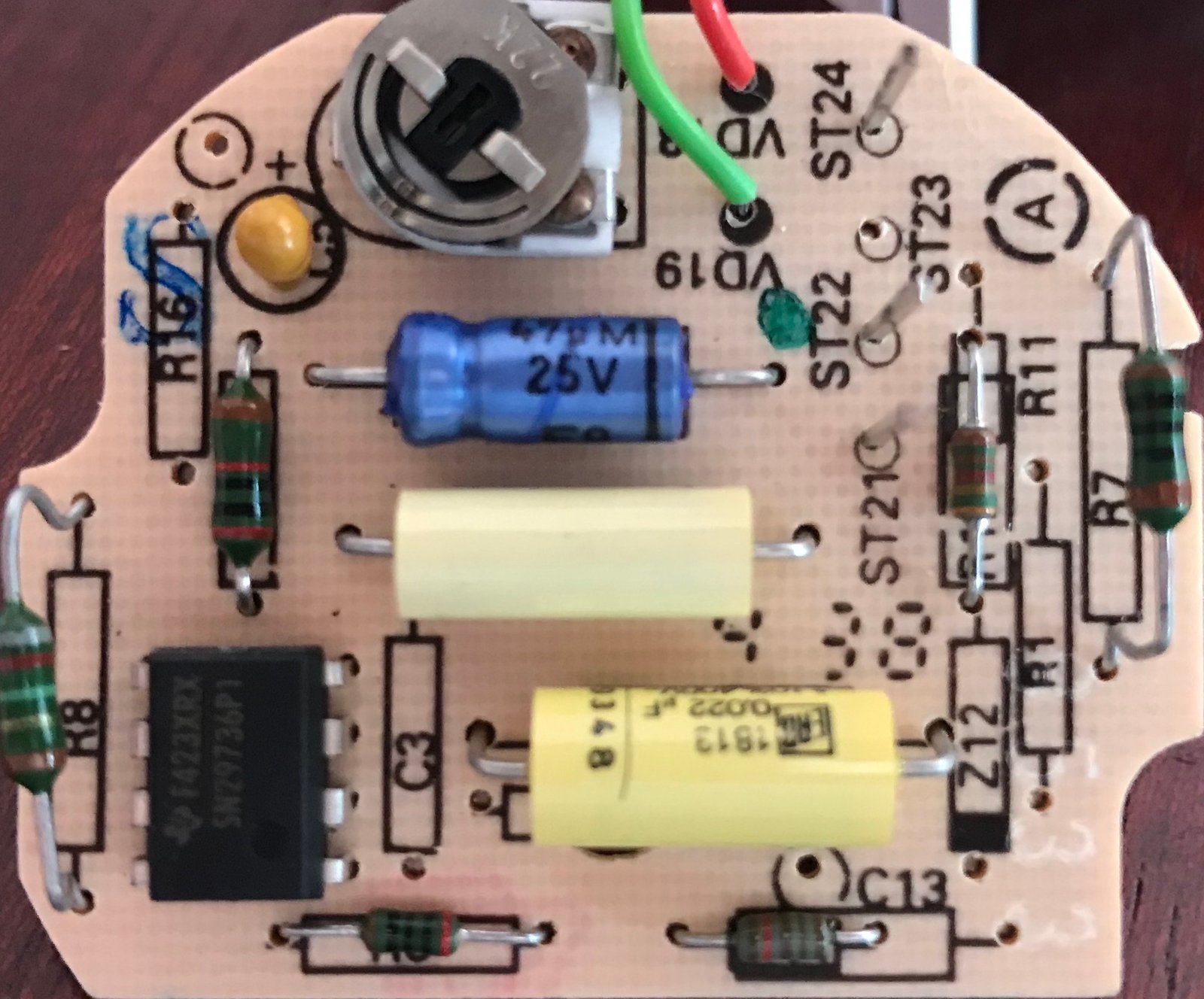
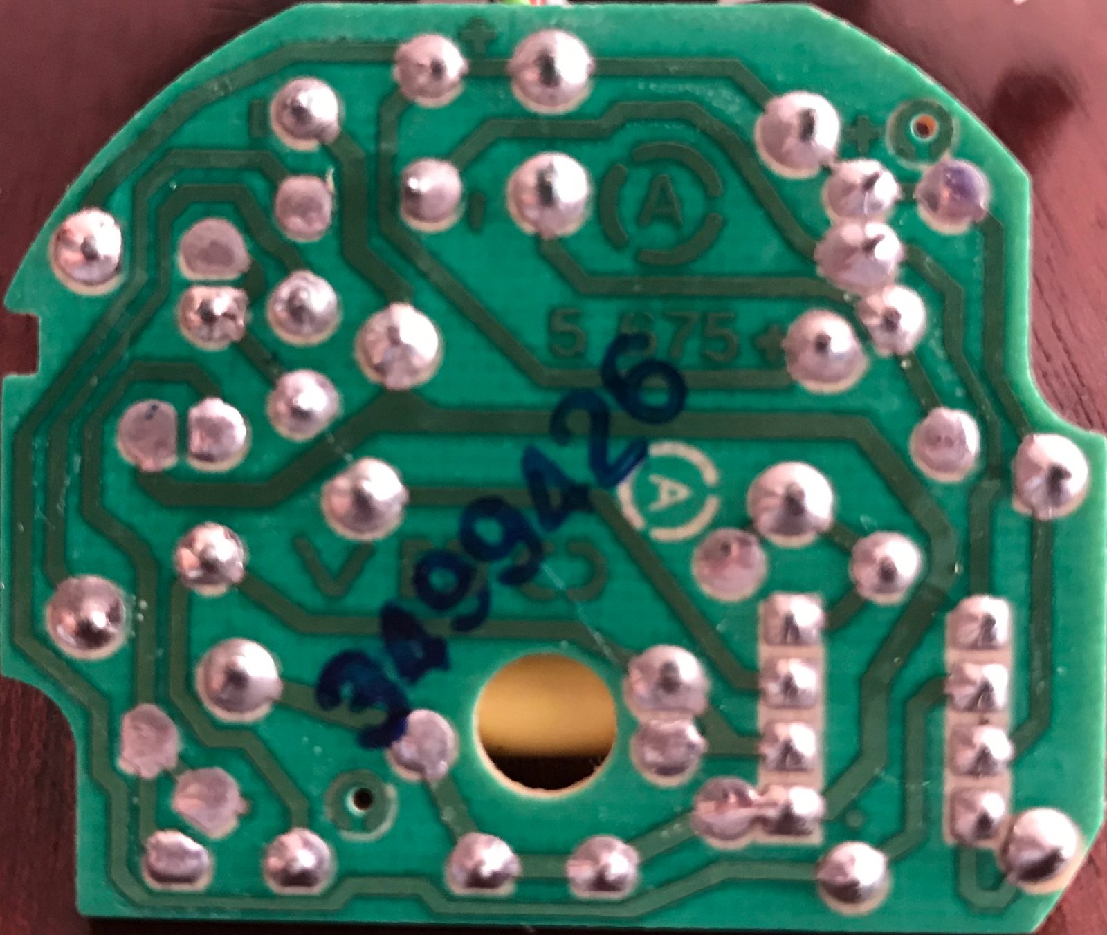
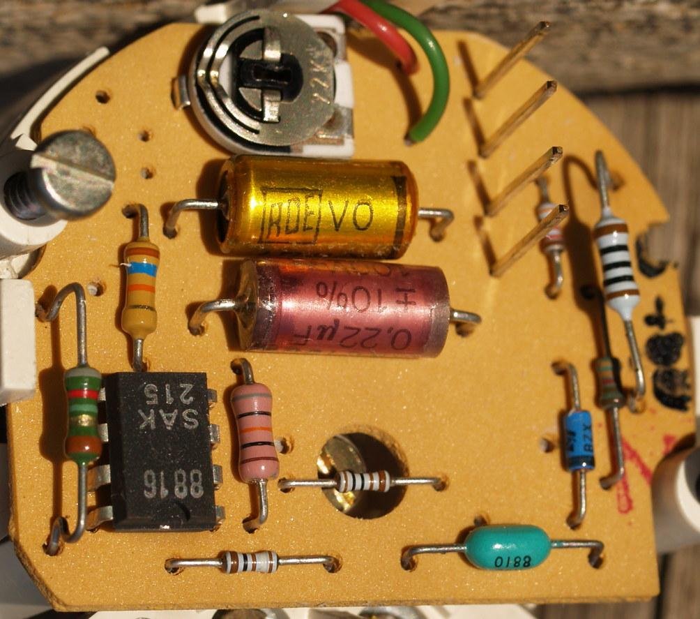
My diesel tacho arrived today, so I took some photos of the circuit board and traced the circuit.

Despite the board being a different shape, the circuit is almost identical to the diesel version I showed in the first post. The IC has a TI part number on it (F423XRX), and I can't find any trace of that online, but the pinouts appear to be the same as the sak215 in the fist post above, and those are readily available (e.g.
here).
The board has various empty component locations, and it seemed likely that it's a common board which gets populated with different components depending on whether it's for petrol or diesel. I haven't yet traced the circuit for the alternative, possibly petrol, configuration. One problem would be knowing what component values to use, as the circuit evidently isn't exactly the same as the petrol schematic in my first post. There's a diode at Z12 for instance, which isn't in the earlier petrol schematic.
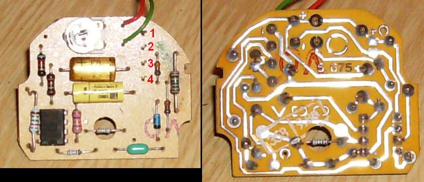
So I turned to Google, and I found a photo of the circuit board from a four cylinder petrol Golf, and sure enough it seems to correspond to the alternative component set on my board. So it should help me to identify all the components.
So then I'd have a choice - I could either use the existing diesel circuit board and reconfigure it to match the Golf version, or I could try to make a replacement PCB. And of course, having discovered how to have PCBs made cheaply, everything seems like a problem best solved with a new PCB at the moment

. And I could leave the diesel version unmolested in case I give up and want to sell the complete diesel tacho on at a later date.
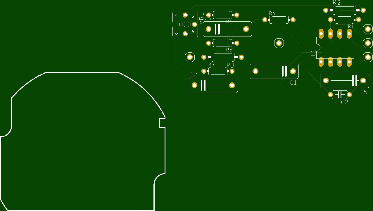
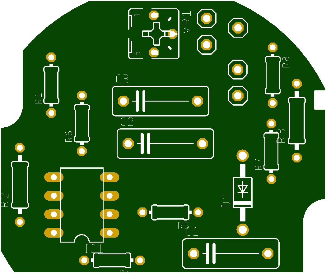
So I made a start by measuring and reproducing the basic PCB shape.

That pile of components next to it needs to be arranged in a similar fashion to the original PCB.
One good thing to come of this - I've been able to test the Dupont sockets on the tacho pins - they fit nice and tight so should be fine as a connection method for my dashboard PCB kit.