Early in this thread 'Midlifecrisis' posted a very clear diagram of the wiring for his 'petrol/no clock' dash. Does anyone know of a similar drawing for the late TD dash with rev counter and digital clock?
If no-one has posted one, I shall carry on trying to work it out for myself. Hopefully this will be in a form suitable for sharing.
Thanks
Replacing the dashboard plastic PCB
Moderators: User administrators, Moderators
-
garyd

- Registered user
- Posts: 486
- Joined: 20 Sep 2006, 18:36
- 80-90 Mem No: 2934
- Location: Wells, Somerset
Re: Replacing the dashboard plastic PCB
Garyd
1990 Transporter syncro camper
2 litre AGG 'GTi' engine
1990 Transporter syncro camper
2 litre AGG 'GTi' engine
-
crazyhorse
- Registered user
- Posts: 864
- Joined: 21 Aug 2013, 15:01
- 80-90 Mem No: 15202
- Location: Llantwit Major, Bro Morganwg, South wales
Re: Replacing the dashboard plastic PCB
Hi gang,
Doing this as my PCB went, rips etc...
I have followed the wiki, to be honest its doing my head in.....
3rd attempt now. So will re do (again) the one in the picture
Couple of questions,
Cutting a track, is it just a case of getting rid of the copper?
does the longest stalk of the led go to the resistor??
what goes where on the back of the coolant and fuel gauge, there are 5 screws??
Lastly 14 pin connector,I have done this, but... I have 4 unaccounted for leads
Green?? - Rev Counter
Red??
White/Red??
Yellow??
Please help a grown man from Crying and thats from someone who has had a "pooh" year up to now...
Doing this as my PCB went, rips etc...
I have followed the wiki, to be honest its doing my head in.....
3rd attempt now. So will re do (again) the one in the picture


Couple of questions,
Cutting a track, is it just a case of getting rid of the copper?
does the longest stalk of the led go to the resistor??
what goes where on the back of the coolant and fuel gauge, there are 5 screws??
Lastly 14 pin connector,I have done this, but... I have 4 unaccounted for leads
Green?? - Rev Counter
Red??
White/Red??
Yellow??
Please help a grown man from Crying and thats from someone who has had a "pooh" year up to now...
-
Oldiebut goodie

- Registered user
- Posts: 7298
- Joined: 18 Apr 2008, 01:19
- 80-90 Mem No: 11135
- Location: Eastern Angle
Re: Replacing the dashboard plastic PCB
Resistor can go to either leg of the led. ( but you must get the polarity of the led correct otherwise it will no worky)
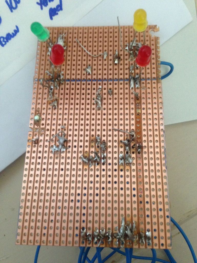
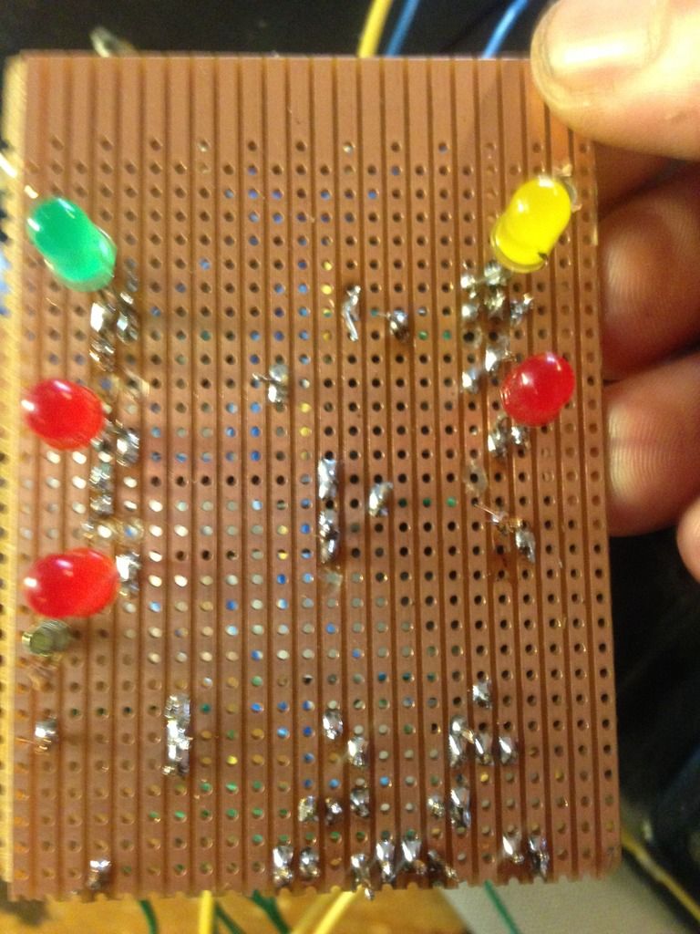
To be blunt - you need to work on your soldering skills, the solder has bridged the tracks in a couple of places that I can see without looking hard. Work under a magnifying lens if you are having trouble seeing what you are doing.
Practice with a gash piece of board and wire, heat the track and wire to be soldered before applying the solder. Make sure that you have cleaned and tinned your bit first otherwise it will be hard to achieve anything. The bit will not transfer the heat easily if it is covered with oxides.
What wattage iron are you using?
Last edited by Oldiebut goodie on 04 Apr 2017, 14:43, edited 2 times in total.
1.6D 2019 VW T-Cross
200hp VW T6
1̶Y̶ ̶1̶9̶8̶7̶ ̶H̶i̶-̶t̶o̶p̶ ̶C̶a̶r̶a̶v̶e̶l̶l̶e̶
5̶0̶8̶d̶ ̶M̶e̶r̶c̶
200hp VW T6
1̶Y̶ ̶1̶9̶8̶7̶ ̶H̶i̶-̶t̶o̶p̶ ̶C̶a̶r̶a̶v̶e̶l̶l̶e̶
5̶0̶8̶d̶ ̶M̶e̶r̶c̶
-
crazyhorse
- Registered user
- Posts: 864
- Joined: 21 Aug 2013, 15:01
- 80-90 Mem No: 15202
- Location: Llantwit Major, Bro Morganwg, South wales
Re: Replacing the dashboard plastic PCB
Oldiebut goodie wrote:Resistor can go to either leg of the led.
To be blunt - you need to work on your soldering skills, the solder has bridged the tracks in a couple of places that I can see without looking hard. Work under a magnifying lens if you are having trouble seeing what you are doing.
Practice with a gash piece of board and wire, heat the track and wire to be soldered before applying the solder. Make sure that you have cleaned and tinned your bit first otherwise it will be hard to acheive anything. The bit will not transfer the heat easily if it is covered with oxides.
Thanks, and thanks for bluntness knew it wasnt the best.
-
crazyhorse
- Registered user
- Posts: 864
- Joined: 21 Aug 2013, 15:01
- 80-90 Mem No: 15202
- Location: Llantwit Major, Bro Morganwg, South wales
Re: Replacing the dashboard plastic PCB
Oldiebut goodie wrote:Resistor can go to either leg of the led. ( but you must get the polarity of the led correct otherwise it will no worky)
To be blunt - you need to work on your soldering skills, the solder has bridged the tracks in a couple of places that I can see without looking hard. Work under a magnifying lens if you are having trouble seeing what you are doing.
Practice with a gash piece of board and wire, heat the track and wire to be soldered before applying the solder. Make sure that you have cleaned and tinned your bit first otherwise it will be hard to achieve anything. The bit will not transfer the heat easily if it is covered with oxides.
What wattage iron are you using?
230, make of Parkside, 'borrowed' it from work.
Is there a way I can test it works without having to put it back on the van??
Have a multimeter also 'borrowed' from work
-
Oldiebut goodie
- Registered user
- Posts: 7298
- Joined: 18 Apr 2008, 01:19
- 80-90 Mem No: 11135
- Location: Eastern Angle
Re: Replacing the dashboard plastic PCB
Parkside is one of the brands sold by Lidl and the like I think.
230 watts? I should think that is the voltage. 18 watt iron is enough for this job.
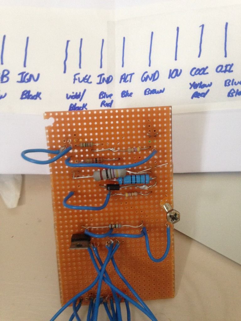
(I am not convinced that you have the voltage regulator in the correct orientation - but it depends upon whether you are using the original VW offering or a replacement which is reversed)
I wouldn't bother with trying it yet not without checking it over making sure that all solder joints are sound and are not joining two tracks. There appears to be extraneous whiskers of wire sprouting around the holes where the wires are inserted - all lead to a chance of them shorting. Neatness with the soldering and wiring will help tracing the circuits through when checking.
This end is extremely suspect

230 watts? I should think that is the voltage. 18 watt iron is enough for this job.
(I am not convinced that you have the voltage regulator in the correct orientation - but it depends upon whether you are using the original VW offering or a replacement which is reversed)
I wouldn't bother with trying it yet not without checking it over making sure that all solder joints are sound and are not joining two tracks. There appears to be extraneous whiskers of wire sprouting around the holes where the wires are inserted - all lead to a chance of them shorting. Neatness with the soldering and wiring will help tracing the circuits through when checking.
This end is extremely suspect
1.6D 2019 VW T-Cross
200hp VW T6
1̶Y̶ ̶1̶9̶8̶7̶ ̶H̶i̶-̶t̶o̶p̶ ̶C̶a̶r̶a̶v̶e̶l̶l̶e̶
5̶0̶8̶d̶ ̶M̶e̶r̶c̶
200hp VW T6
1̶Y̶ ̶1̶9̶8̶7̶ ̶H̶i̶-̶t̶o̶p̶ ̶C̶a̶r̶a̶v̶e̶l̶l̶e̶
5̶0̶8̶d̶ ̶M̶e̶r̶c̶
-
slowcoach

- Registered user
- Posts: 1588
- Joined: 06 May 2010, 10:23
- 80-90 Mem No: 8892
- Location: West Yorkshire
- Contact:
Re: Replacing the dashboard plastic PCB
For bench testing it out of the van, you can just carefully apply 12v to the tracks you're testing, ie alt light, while grounding the ground track to the same battery. Just careful not to short anything by brushing the wires against anything.
Sent from my MotoG3 using Tapatalk
Sent from my MotoG3 using Tapatalk
===================
1984 TRAKKA Conversion Subaru EJ20 5 Speed
1984 TRAKKA Conversion Subaru EJ20 5 Speed
-
boatbuilder
- Registered user
- Posts: 804
- Joined: 09 Aug 2009, 21:53
- 80-90 Mem No: 8265
- Location: County Monaghan, Ireland
Re: Replacing the dashboard plastic PCB
I found it easier to put the whole 10v wiring on a small separate board and mount it on the top of the right hand clock housing with some foam tape.. Makes the main board less complicated and easier to get your head round.
Plus if/when your 10v regulator goes pop, it's easy to get to.
Sent from my SM-G920F using Tapatalk
Plus if/when your 10v regulator goes pop, it's easy to get to.
Sent from my SM-G920F using Tapatalk
1984 1.9D (AEF Code) T25 tintop
-
crazyhorse
- Registered user
- Posts: 864
- Joined: 21 Aug 2013, 15:01
- 80-90 Mem No: 15202
- Location: Llantwit Major, Bro Morganwg, South wales
Re: Replacing the dashboard plastic PCB
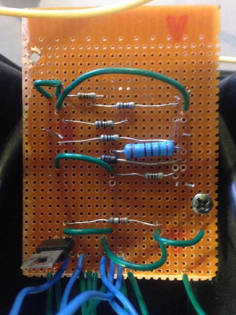
Right then take 3 ready to rock.
Reused regulator from old cluster.
Tested main beam out of van, that worked.
Made sure no solder crossed onto separate track
We shall see
Reused regulator from old cluster.
Tested main beam out of van, that worked.
Made sure no solder crossed onto separate track
We shall see


-
Oldiebut goodie
- Registered user
- Posts: 7298
- Joined: 18 Apr 2008, 01:19
- 80-90 Mem No: 11135
- Location: Eastern Angle
Re: Replacing the dashboard plastic PCB
That's looking better. 
1.6D 2019 VW T-Cross
200hp VW T6
1̶Y̶ ̶1̶9̶8̶7̶ ̶H̶i̶-̶t̶o̶p̶ ̶C̶a̶r̶a̶v̶e̶l̶l̶e̶
5̶0̶8̶d̶ ̶M̶e̶r̶c̶
200hp VW T6
1̶Y̶ ̶1̶9̶8̶7̶ ̶H̶i̶-̶t̶o̶p̶ ̶C̶a̶r̶a̶v̶e̶l̶l̶e̶
5̶0̶8̶d̶ ̶M̶e̶r̶c̶
-
slowcoach
- Registered user
- Posts: 1588
- Joined: 06 May 2010, 10:23
- 80-90 Mem No: 8892
- Location: West Yorkshire
- Contact:
Re: Replacing the dashboard plastic PCB
Thumbs up 
Sent from my MotoG3 using Tapatalk
Sent from my MotoG3 using Tapatalk
===================
1984 TRAKKA Conversion Subaru EJ20 5 Speed
1984 TRAKKA Conversion Subaru EJ20 5 Speed
-
crazyhorse
- Registered user
- Posts: 864
- Joined: 21 Aug 2013, 15:01
- 80-90 Mem No: 15202
- Location: Llantwit Major, Bro Morganwg, South wales
Re: Replacing the dashboard plastic PCB
Cheers guys, I feel acceptance and warmness.
But,
it still doesnt f*&**%g work. Bloody hell.
Light comes on coolant, nothing else,led lights look sentive. it's hard soldering those bad boys on.
If the coolant light works for self check, does that mean the regulator is OK?? Nothing on fuel gauge.
Going to try one more time
But,
it still doesnt f*&**%g work. Bloody hell.
Light comes on coolant, nothing else,led lights look sentive. it's hard soldering those bad boys on.
If the coolant light works for self check, does that mean the regulator is OK?? Nothing on fuel gauge.
Going to try one more time
-
MidLifeCrisis
- Registered user
- Posts: 566
- Joined: 20 Nov 2011, 19:07
- 80-90 Mem No: 10519
- Location: Bagshot, Surrey
Re: Replacing the dashboard plastic PCB
Keep up the good work - I'm working on your Plan B tonight!
If the coolant light works that is a good bet that the 10V reg is working - but then the fuel gauge should work - all that needs is a good 10V and the fuel sender signal!?!
If the coolant light works that is a good bet that the 10V reg is working - but then the fuel gauge should work - all that needs is a good 10V and the fuel sender signal!?!
1987 Westfalia Van, Petrol 2.0 AGG
-
crazyhorse
- Registered user
- Posts: 864
- Joined: 21 Aug 2013, 15:01
- 80-90 Mem No: 15202
- Location: Llantwit Major, Bro Morganwg, South wales
Re: Replacing the dashboard plastic PCB
MidLifeCrisis wrote:Keep up the good work - I'm working on your Plan B tonight!
If the coolant light works that is a good bet that the 10V reg is working - but then the fuel gauge should work - all that needs is a good 10V and the fuel sender signal!?!
thanks.
Just to confirm, for the fuel gauge, on the back of the dash, which one is 10v and which one is the sender??
-
MidLifeCrisis
- Registered user
- Posts: 566
- Joined: 20 Nov 2011, 19:07
- 80-90 Mem No: 10519
- Location: Bagshot, Surrey
Re: Replacing the dashboard plastic PCB
crazyhorse wrote: Just to confirm, for the fuel gauge, on the back of the dash, which one is 10v and which one is the sender??
This layout shows the position of the fuel gauge screws - it oriented as if you are looking at the back of the gauge

Relate the drawing to this if it helps ....

1987 Westfalia Van, Petrol 2.0 AGG