
Thank you - it's not a problem to have a single current-limiting resistor, provided all three LEDs are identical, and the resistor would be chosen to limit the current to 3x the amount that each LED requires. I'll work on this tomorrow. I'll add a jumper to choose 'direct' or 'via resistors'. It'll be easier to fit one additional resistor, but I'd prefer to squeeze in three extra resistors, so that the LEDs can be different, and so that there's no problem if one fails.
Replacing the dashboard plastic PCB
Moderators: User administrators, Moderators
Re: Replacing the dashboard plastic PCB
Thank you - it's not a problem to have a single current-limiting resistor, provided all three LEDs are identical, and the resistor would be chosen to limit the current to 3x the amount that each LED requires. I'll work on this tomorrow. I'll add a jumper to choose 'direct' or 'via resistors'. It'll be easier to fit one additional resistor, but I'd prefer to squeeze in three extra resistors, so that the LEDs can be different, and so that there's no problem if one fails.
"I'm a man of means, by no means....King of the Road!"
1983 Viking Xplorer, 2.1DJ
1983 Viking Xplorer, 2.1DJ
-
CovKid

- Trader
- Posts: 8409
- Joined: 30 Apr 2006, 13:19
- 80-90 Mem No: 3529
- Location: Ralph - Coventry (Retired)
- Contact:
Re: Replacing the dashboard plastic PCB
Way to go Chris 
Roller paint your camper at home: http://roller.epizy.com/55554/" onclick="window.open(this.href);return false; for MP4 download.
Re: Replacing the dashboard plastic PCB
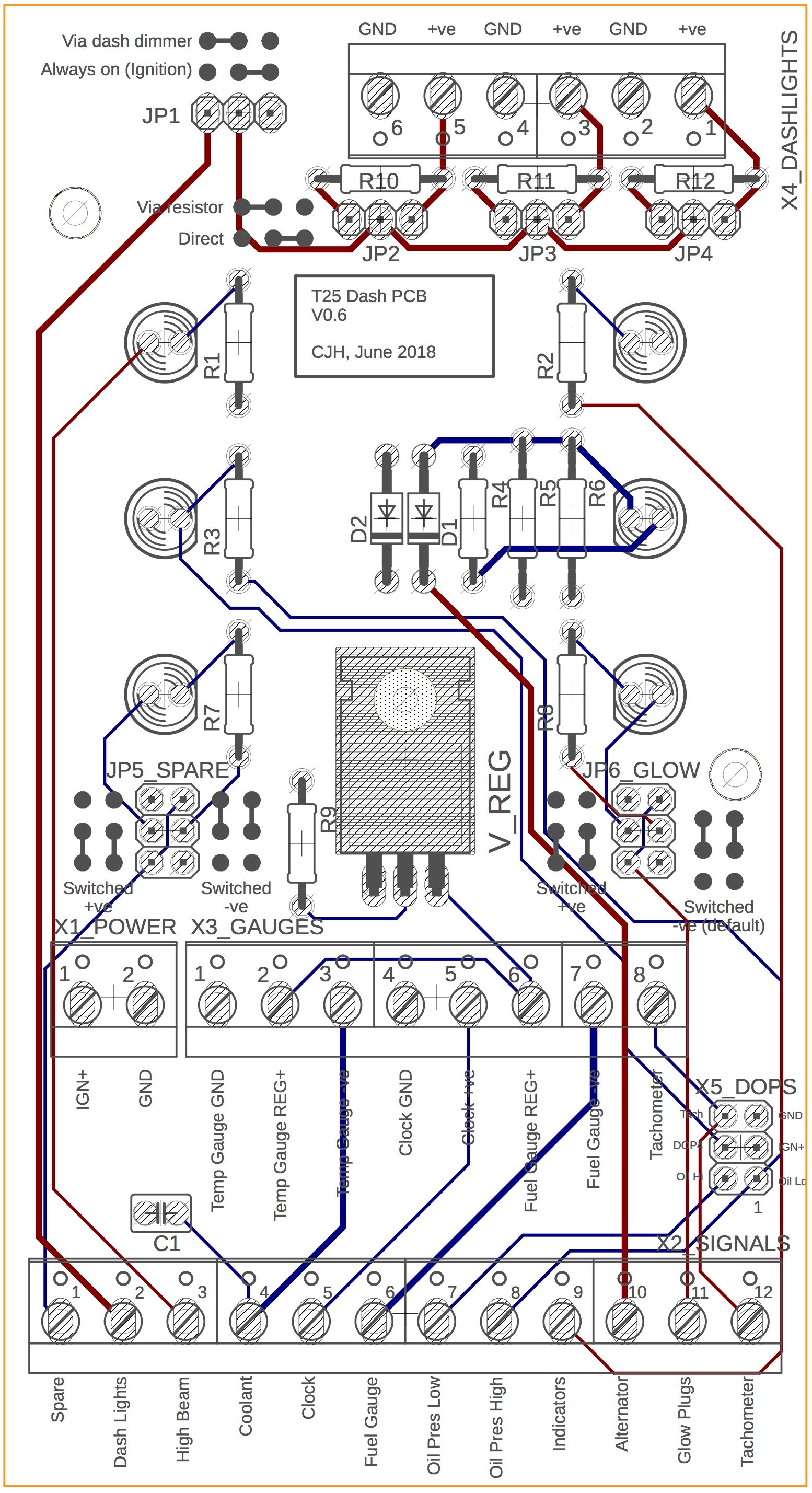
Three separate resistors means three separate jumpers - couldn't see another way. So the board had to grow a few mm at the top edge, but now each dash bulb can be configured separately, with it's own resistor that can be switched in or out of the circuit. There's still a common source for all three though, either ignition-controlled or via the dimmer.
So unless someone tells me that I've misinterpreted the circuit for diode D2, or spots some other blunder, then I'll place the order for this and the multiplug adapter later today.
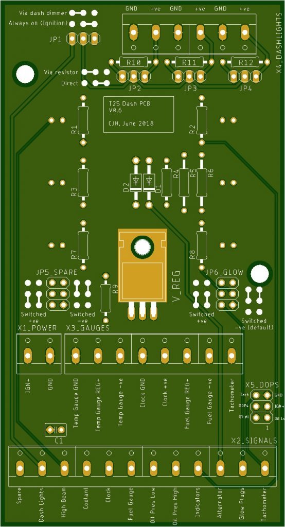

So unless someone tells me that I've misinterpreted the circuit for diode D2, or spots some other blunder, then I'll place the order for this and the multiplug adapter later today.
"I'm a man of means, by no means....King of the Road!"
1983 Viking Xplorer, 2.1DJ
1983 Viking Xplorer, 2.1DJ
Re: Replacing the dashboard plastic PCB
ghost123uk wrote: Also, is there a 22 Ohm resistor from the 10 Volt reg to earth on the original? There may be, but it's not usual practice with a simple 3 leg V reg.
I've just noticed that my resistor R9 is redundant if I'm going to lie the regulator down directly onto the ground plane (assuming the centre pin and the backing are electrically connected inside the regulator package). So in that case I have the choice to isolate that little patch of ground plane and connect it to GND via that same resistor, or just remove that resistor altogether and let the regulator take advantage of the entire ground plane for heat dissipation. Based on Ghost's comment above I'm inclined to just delete the resistor, but again, would welcome any advice.
"I'm a man of means, by no means....King of the Road!"
1983 Viking Xplorer, 2.1DJ
1983 Viking Xplorer, 2.1DJ
Re: Replacing the dashboard plastic PCB
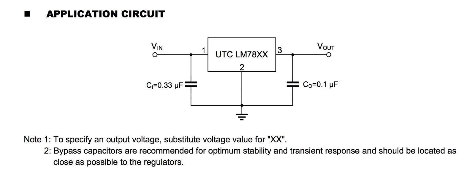
I checked the application note for a typical LM7810 - no sign of that ground pin resistor, but it does mention a couple of bypass capacitors for 'optimum stability'.
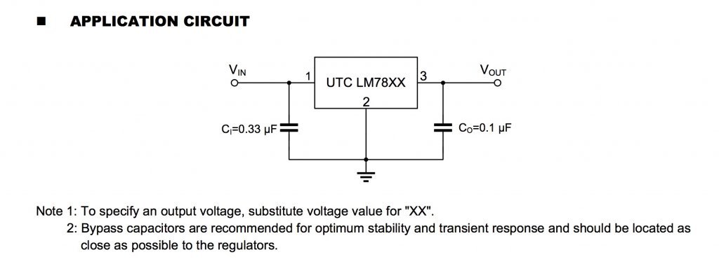
Not sure how important it is to have 'optimum stability' for the fuel and temperature gauges, but no harm in adding the option to fit them.

Not sure how important it is to have 'optimum stability' for the fuel and temperature gauges, but no harm in adding the option to fit them.
"I'm a man of means, by no means....King of the Road!"
1983 Viking Xplorer, 2.1DJ
1983 Viking Xplorer, 2.1DJ
Re: Replacing the dashboard plastic PCB
I've been digging a bit more into this regulator. Some thoughts/questions:
The only purpose I can see for the resistor on the ground pin in the original flexible PCB is to limit the current, and at 22 ohms and a maximum input voltage of 14.5V, then the current would be limited to 0.66A. But the fuel gauge and the temperature gauge each draw 0.1A at nominal mid-scale values (according to Angelo's earlier post), so why would we need to limit the current to >3x the sum of these? Is it because those gauges can have a much lower resistance at one or other ends of the scale? Is it to protect the regulator against a short somewhere? If so, then I think some of the modern alternatives to the original regulator have short circuit and polarity protection built in. Keep in mind that just because I said that's the only purpose *I can see*, it doesn't mean it's the only purpose there is.
I took the advice earlier in this thread to use an LM8210 regulator, but I've seen reference elsewhere to the use of an LM2940, which is a low drop-out (LDO) regulator, meaning it will provide 10V even if the input voltage isn't very much higher (I think 10.5V is the absolute minimum). The LM8210 isn't an LDO, and needs at least 2V margin I think. So I know that the input voltage will rarely be as low as 12V, but is there any other reason that the much more expensive LM2940 would be a benefit? The TI LM2940 seems to have short circuit and reverse polarity protection, whereas some cheaper LM8210 units don't. Is this important? Once it's wired up correctly, a short or reverse polarity would seem to be next to impossible.
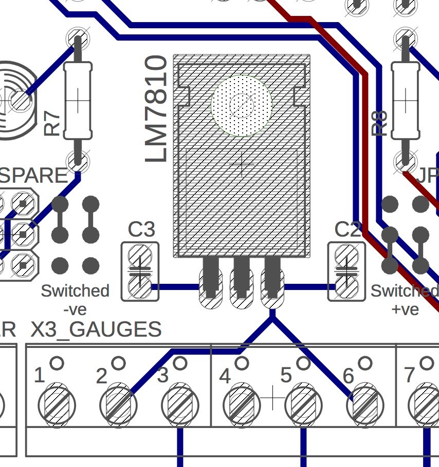
I'm reasonably happy about the cooling of the regulator now. I did the sums according to Texas Instruments' spec sheet for the LM2940, and even at 14.5V input it shouldn't need an extra heat sink, so when it's fixed to the ground plane it should be fine - might make the whole PCB a bit warm. Interestingly, the LM2940, which seems to be specified as the replacement for the NLA original TCA700Y, has the pins reversed, so when it's tuned round and screwed to the original flexible PCB the back of the package no longer makes contact with the original heatsink surface. But then it doesn't really look like a thermal surface anyway:

There must be someone out there who knows more about this than me, so some thoughts on the regulator resistor and choice of regulator would be appreciated. Same goes for that odd diode that I can't see the need for.
The only purpose I can see for the resistor on the ground pin in the original flexible PCB is to limit the current, and at 22 ohms and a maximum input voltage of 14.5V, then the current would be limited to 0.66A. But the fuel gauge and the temperature gauge each draw 0.1A at nominal mid-scale values (according to Angelo's earlier post), so why would we need to limit the current to >3x the sum of these? Is it because those gauges can have a much lower resistance at one or other ends of the scale? Is it to protect the regulator against a short somewhere? If so, then I think some of the modern alternatives to the original regulator have short circuit and polarity protection built in. Keep in mind that just because I said that's the only purpose *I can see*, it doesn't mean it's the only purpose there is.
I took the advice earlier in this thread to use an LM8210 regulator, but I've seen reference elsewhere to the use of an LM2940, which is a low drop-out (LDO) regulator, meaning it will provide 10V even if the input voltage isn't very much higher (I think 10.5V is the absolute minimum). The LM8210 isn't an LDO, and needs at least 2V margin I think. So I know that the input voltage will rarely be as low as 12V, but is there any other reason that the much more expensive LM2940 would be a benefit? The TI LM2940 seems to have short circuit and reverse polarity protection, whereas some cheaper LM8210 units don't. Is this important? Once it's wired up correctly, a short or reverse polarity would seem to be next to impossible.
I'm reasonably happy about the cooling of the regulator now. I did the sums according to Texas Instruments' spec sheet for the LM2940, and even at 14.5V input it shouldn't need an extra heat sink, so when it's fixed to the ground plane it should be fine - might make the whole PCB a bit warm. Interestingly, the LM2940, which seems to be specified as the replacement for the NLA original TCA700Y, has the pins reversed, so when it's tuned round and screwed to the original flexible PCB the back of the package no longer makes contact with the original heatsink surface. But then it doesn't really look like a thermal surface anyway:
There must be someone out there who knows more about this than me, so some thoughts on the regulator resistor and choice of regulator would be appreciated. Same goes for that odd diode that I can't see the need for.
"I'm a man of means, by no means....King of the Road!"
1983 Viking Xplorer, 2.1DJ
1983 Viking Xplorer, 2.1DJ
-
AngeloEvs

- Registered user
- Posts: 1345
- Joined: 22 Nov 2007, 19:22
- 80-90 Mem No: 4709
- Location: Upwell, Norfolk
Re: Replacing the dashboard plastic PCB
Resistors and Diodes are inserted into the Earth leg to raise the output voltage of the regulator. the output of this type of fixed regulator is always referenced to the voltage on the ground connection which does not have to necessarily be 0v. E.g, if you wanted a output of 5.6V from a 5v Regulator a silicon diode can be inserted between the regulators ground connection and actual ground, the diode when forward biased, would drop 0.6V across it and the output is thus 5.6V. Similarly, adding a resistor will cause a volts drop across it and, what ever that Vdrop is, is added to the actual output voltage. The Vdrop across the resistor will vary with the current flowing through it and the load current of the regulator. The 22 ohm will raise the output slightly.
It is worth pointing out that the Temp Gauge warning LED internal circuit false triggers if the regulator output voltage drops to around 9.7V, you can test this on a bench with a variable PSU feeding the gauges. I can only think that the reason for incorporating the 22 ohm resistor is to raise the output slightly above 10V.
The diode across the 12v to 0V supply is referred to as a 'clamping diode', its function is to supress any negative transients that could appear on the 12v supply. Once again, the only components that could be adversley affected by high value negative transienst are the DOPs PCB and the the Temp Gauge internal circuit which activates when negative pulses are injected from the LSCU module 43 into the temp gauge output circuit. It could theoretically be possible for negative transients to cause the temp gauge to false triggering but thats just a theoretical assesment on my part. Devices suach as relays cause negative transients or 'back E.M.F' and there are a lot of them in our vans.
1987 DG Karisma LPG with remodelled interior
Re: Replacing the dashboard plastic PCB
Thanks Angelo, that's a very useful explanation. So I'll reinstate the resistor on the ground pin of the regulator, to avoid false alarms on the temperature gauge. It'll mean isolating that patch of ground plane that the regulator sits on - I'll see if I can work out how to do that, and I'll try to make that patch as big as possible so that it still has some heatsink capability.
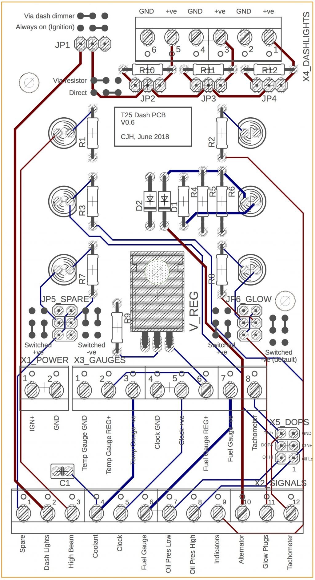
And I'll leave that clamping diode in place. If you look at my images above, you'll see that there aren't any traces coming from either of the diode's pads - that's because it connects to the ground plane at one end and the Ignition plane at the other. Is it right that it just sits between those two planes?
And I'll leave that clamping diode in place. If you look at my images above, you'll see that there aren't any traces coming from either of the diode's pads - that's because it connects to the ground plane at one end and the Ignition plane at the other. Is it right that it just sits between those two planes?
"I'm a man of means, by no means....King of the Road!"
1983 Viking Xplorer, 2.1DJ
1983 Viking Xplorer, 2.1DJ
-
AngeloEvs
- Registered user
- Posts: 1345
- Joined: 22 Nov 2007, 19:22
- 80-90 Mem No: 4709
- Location: Upwell, Norfolk
Re: Replacing the dashboard plastic PCB
Diode across 12v and 0 is fine. The heatsink will sit on top of the board so it should be insulated from ground 0v anyway. All that remains is to ensure that the other side of the pcb where any securing screws, etc, has a small area around the fixing hole devoid of copper plate. That is how it is normally done.
1987 DG Karisma LPG with remodelled interior
Re: Replacing the dashboard plastic PCB
The component side of the board has a GND plane over the entire surface (with isolation gaps to separate any traces on that side). By default, any part of the board that doesn't have pads is covered with solder stop, so I had created a small rectangle on the 'tstop' layer to prevent solder stop covering the copper ground plane under the regulator, so that the regulator would sit directly on the copper of the ground plane. I thought this would give good thermal contact, and allow the whole ground plane to act as the heatsink.AngeloEvs wrote: The heatsink will sit on top of the board so it should be insulated from ground 0v anyway.
So I could do as you suggest, and put the solder stop back, so that the back of the regulator doesn't make electrical contact with the ground plane, but then the thermal contact wouldn't be as good. Would it be sufficient do you think?
"I'm a man of means, by no means....King of the Road!"
1983 Viking Xplorer, 2.1DJ
1983 Viking Xplorer, 2.1DJ
-
AngeloEvs
- Registered user
- Posts: 1345
- Joined: 22 Nov 2007, 19:22
- 80-90 Mem No: 4709
- Location: Upwell, Norfolk
Re: Replacing the dashboard plastic PCB
Given the space limitation, the normal practice is to use a T220 insulating washer, usually mica but there are polymer alternatives. Normally a silicon heatsink compound is added to aid conduction but you could probably get away without it. Alternatively, isolate a section of the copper area where the regulator is fitted. You dont need much of a heatsink capability for this application.
1987 DG Karisma LPG with remodelled interior
Re: Replacing the dashboard plastic PCB
Thanks Angelo
I went with re-applying the solder mask, and clearing the copper from around the bolt hole, and I've now placed the order for the first prototype. It's bound to need at least a second iteration, so I'll use this first version to see whether any additional heatsink capacity is needed. Thanks for all your help.
I went with re-applying the solder mask, and clearing the copper from around the bolt hole, and I've now placed the order for the first prototype. It's bound to need at least a second iteration, so I'll use this first version to see whether any additional heatsink capacity is needed. Thanks for all your help.
"I'm a man of means, by no means....King of the Road!"
1983 Viking Xplorer, 2.1DJ
1983 Viking Xplorer, 2.1DJ
Re: Replacing the dashboard plastic PCB
This factory in Shenzen evidently operates a 24 hour shift system. I uploaded the PCB files around 10pm yesterday, and already the boards are half finished:
1 MI: 2018-06-04 04:42:43
2 Drilling: 2018-06-04 06:53:21
3 Copper Deposition: 2018-06-04 10:22:12
4 Image the outer layers: 2018-06-04 10:53:15
5 Pattern Plating: 2018-06-04 12:44:00
6 Automatic Optical Inspection(AOI): 2018-06-04 15:32:29
7 Solder Mask: 2018-06-04 15:42:25
Times appear to be UK times. That last process, at 15:42 UK time, actually took place just before midnight in Shenzen.
Remaining processes:
8 Silkscreen
9 Hot Air Solder Leveling(HASL)
10 Electrical Test
11 Profiling,V-cut scoring
12 Final inspection
13 Packaging,Delivery
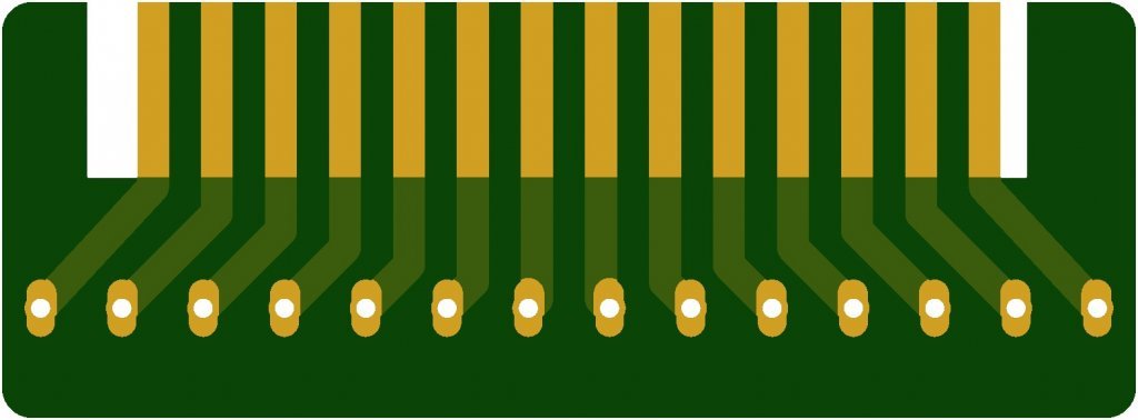
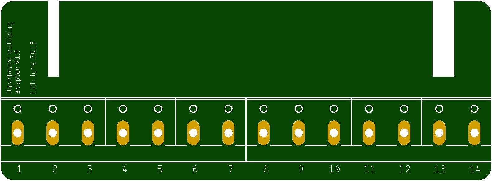
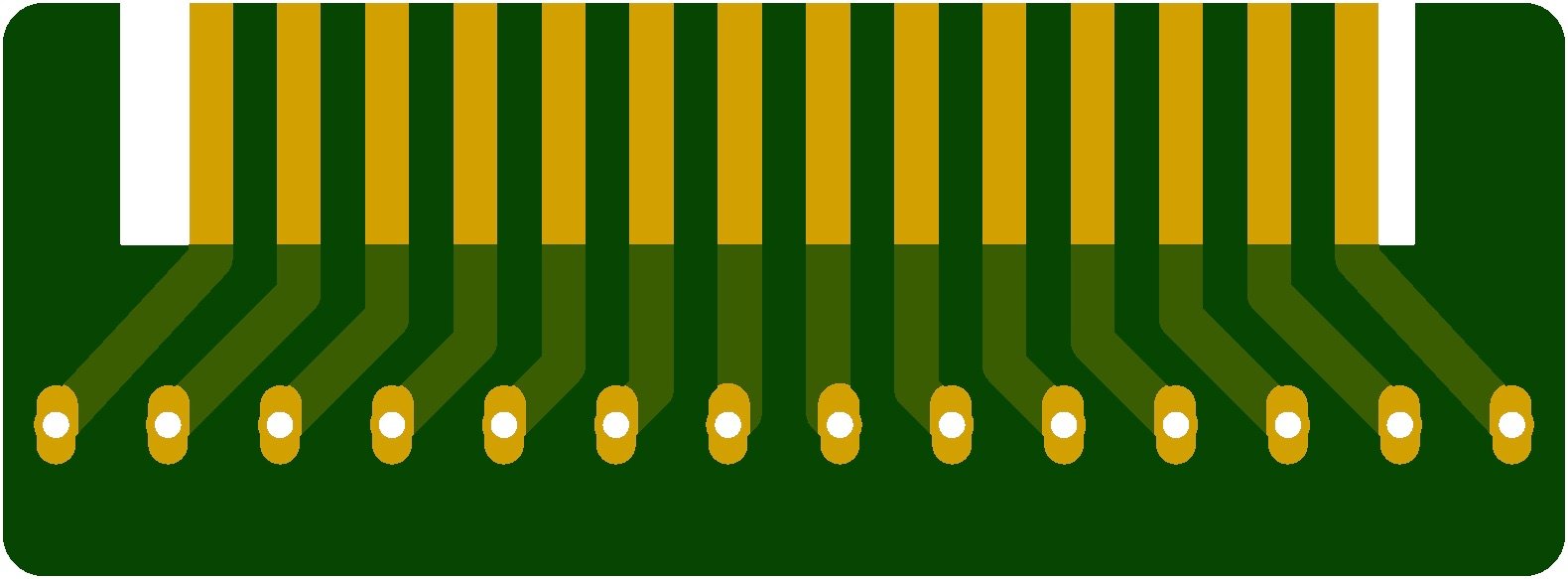
The 'fingers' board, submitted at the same time, is a bit behind (not far), and I think that's because having the copper go right to the edge of the board breaks their automatic rules, and probably required a supervisor to OK the files according to my instructions. It'll also have a different (gold) finish, instead of the 'HASL' in step 9, to make the fingers more resilient to physical damage and corrosion.
1 MI: 2018-06-04 04:42:43
2 Drilling: 2018-06-04 06:53:21
3 Copper Deposition: 2018-06-04 10:22:12
4 Image the outer layers: 2018-06-04 10:53:15
5 Pattern Plating: 2018-06-04 12:44:00
6 Automatic Optical Inspection(AOI): 2018-06-04 15:32:29
7 Solder Mask: 2018-06-04 15:42:25
Times appear to be UK times. That last process, at 15:42 UK time, actually took place just before midnight in Shenzen.
Remaining processes:
8 Silkscreen
9 Hot Air Solder Leveling(HASL)
10 Electrical Test
11 Profiling,V-cut scoring
12 Final inspection
13 Packaging,Delivery
The 'fingers' board, submitted at the same time, is a bit behind (not far), and I think that's because having the copper go right to the edge of the board breaks their automatic rules, and probably required a supervisor to OK the files according to my instructions. It'll also have a different (gold) finish, instead of the 'HASL' in step 9, to make the fingers more resilient to physical damage and corrosion.
"I'm a man of means, by no means....King of the Road!"
1983 Viking Xplorer, 2.1DJ
1983 Viking Xplorer, 2.1DJ
-
CovKid
- Trader
- Posts: 8409
- Joined: 30 Apr 2006, 13:19
- 80-90 Mem No: 3529
- Location: Ralph - Coventry (Retired)
- Contact:
Re: Replacing the dashboard plastic PCB
A fun diversion for you Chris. How NOT to build a temperature controller 
https://www.youtube.com/watch?v=78zYtjTm2yY" onclick="window.open(this.href);return false;
https://www.youtube.com/watch?v=78zYtjTm2yY" onclick="window.open(this.href);return false;
Roller paint your camper at home: http://roller.epizy.com/55554/" onclick="window.open(this.href);return false; for MP4 download.
Re: Replacing the dashboard plastic PCB
"It's interesting because it's such a bad design"
"You can't just stick loads of modules together and expect it to work"
Please don't send him my dashboard PCB. Although in mitigation, my dashboard PCB doesn't have any logic circuits or low voltage stuff that's going to be sensitive to noise. It's basically just wires laid out as nice fat copper tracks.
The PCBs are finished now - they just need to be wheeled across the road (or to the other side of the factory) to be matched up with the parts order, and then they'll be shipped off with DHL - should have them by the weekend with a bit of luck.
"I'm a man of means, by no means....King of the Road!"
1983 Viking Xplorer, 2.1DJ
1983 Viking Xplorer, 2.1DJ